Toyota Tacoma (2015-2018) Service Manual: System Description
SYSTEM DESCRIPTION
1. SRS (SUPPLEMENTAL RESTRAINT SYSTEM) AIRBAG SYSTEM
(a) General Description
(1) The SRS airbag system consists of the following airbag and main components:
|
Airbag |
Access Cab Model |
Double Cab Model |
|---|---|---|
|
Driver Airbag |
Standard |
Standard |
|
Front Passenger Airbag |
Standard |
Standard |
|
Knee Airbag |
Standard |
Standard |
|
Side Airbag |
Standard |
Standard |
|
Curtain Shield Airbag |
Standard |
Standard |
|
Main Components |
Features |
|---|---|
|
Airbag Sensor Assembly |
|
|
Occupant Detection ECU |
Determines front passenger seat occupant conditions through occupant classification sensors |
|
Front Airbag Sensor |
Detect intensity of frontal collisions though electrical deceleration sensor |
|
Side Airbag Sensor Assembly |
Detect intensity of side collision through electrical deceleration sensor |
|
Rear Airbag Sensor |
Detect intensity of side rear collision through electrical deceleration sensor |
|
Occupant Classification Sensors |
Detect occupant weight on front passenger seat |
|
Seat Position Airbag Sensor |
Detects driver seat position |
|
Seat Belt Buckle Switches |
Detect whether of not seat belt fastened |
|
Airbag ON/OFF Indicator |
Illuminates ON or OFF light to indicate front and side passenger airbag deployment availability |
|
SRS Warning Light |
Illuminates to indicate existence of malfunctions in SRS airbag system |
2. AIRBAG DEPLOYMENT
(a) Front Collisions
(1) The driver and front passenger airbags are in case of frontal collisions. These airbags deploy by dual stage control. In order to activate dual stage control, the airbag sensor assembly monitors the following information through the components shown in the table below:
|
Seat |
Information |
Models with Separate Seat |
|---|---|---|
|
Driver |
Intensity of Impact |
Same As Left |
|
Driver |
Driver Seat Position |
Same As Left |
|
Driver |
Seat Belt Position |
Same As Left |
|
Front Passenger |
Intensity of Impact |
Same As Left |
|
Front Passenger |
Occupant Weight |
Four Occupant Classification Sensors |
|
Front Passenger |
Seat Belt Condition |
Same As Left |
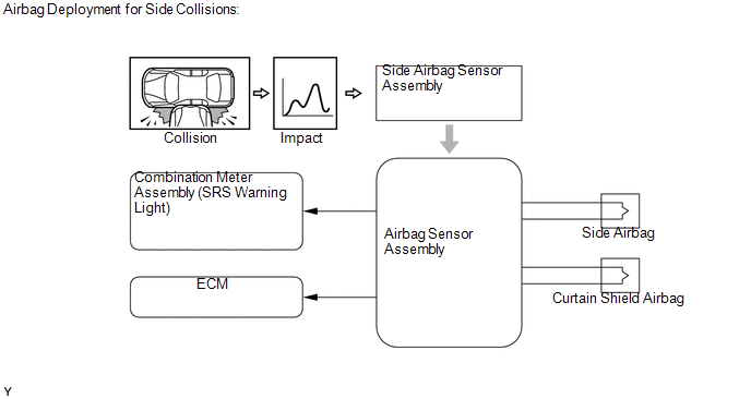
(b) Side Collisions
(1) The side and curtain shield airbags are in case of side collisions. The side airbags are installed in the seat backs of the driver seat and the front passenger seat, and the curtain shield airbags are installed in the upper areas of the right and left center pillars. If a side airbag sensor assembly detects an impact, the airbag sensor assembly causes the side and curtain shield airbags to be deployed simultaneously.
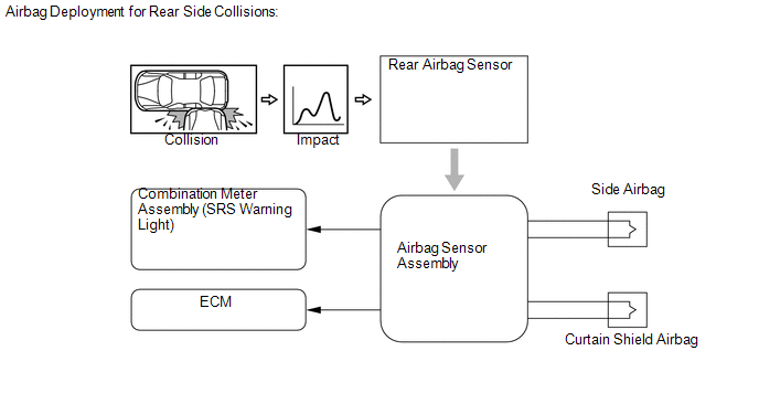
(c) Rear Side Collisions
(1) The side and curtain shield airbags are in case of rear side collisions. The side airbags are installed in the seat backs of the driver seat and the front passenger seat, and the curtain shield airbags are installed in the upper areas of the right and left center pillars. If a side airbag sensor assembly detects an impact, the airbag sensor assembly causes the side and curtain shield airbags to be deployed simultaneously.
 Problem Symptoms Table
PROBLEM SYMPTOMS TABLE
HINT:
Use the table below to help determine the cause of problem symptoms.
If multiple suspected areas are listed, the potential causes of the symptoms
are lis ...
 Check Mode Procedure
CHECK MODE PROCEDURE
1. Check Mode (Signal Check): DTC CHECK
(a) Connect the Techstream to the DLC3.
(b) Turn the ignition switch to ON and turn the Techstream on.
(c) Select the Signal Check on t ...
Other materials:
Registration
REGISTRATION
PROCEDURE
1. DESCRIPTION OF CODE REGISTRATION
HINT:
Registering an ID code enables the entry and start function, wireless
door lock control function and engine immobiliser function to be operated.
Code registration is needed when the certification ECU (smart key E ...
Destination Information Undefined (C1AB8)
DESCRIPTION
This DTC is stored when correct destination information is not sent from the
main body ECU (multiplex network body ECU) and destination information cannot be
confirmed after a blind spot monitor has been replaced.
DTC Code
DTC Detection Condition
Tr ...
Terminals Of Ecu
TERMINALS OF ECU
1. CHECK AIR CONDITIONING AMPLIFIER ASSEMBLY (for Automatic Air Conditioning)
(See page )
2. CHECK AIR CONDITIONING AMPLIFIER ASSEMBLY (for Manual Air Conditioning)
(See page )
3. CHECK AIR CONDITIONING CONTROL ASSEMBLY (for Automatic Air Conditioning)
(See page )
4. CHECK ...
