Toyota Tacoma (2015-2018) Service Manual: System Diagram
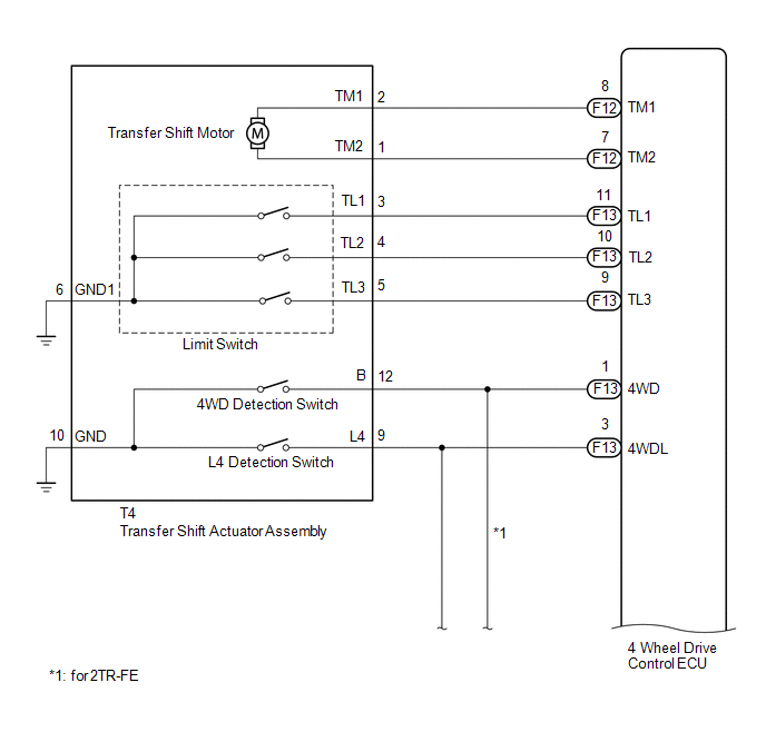
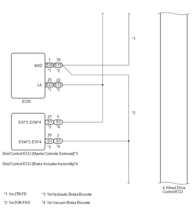
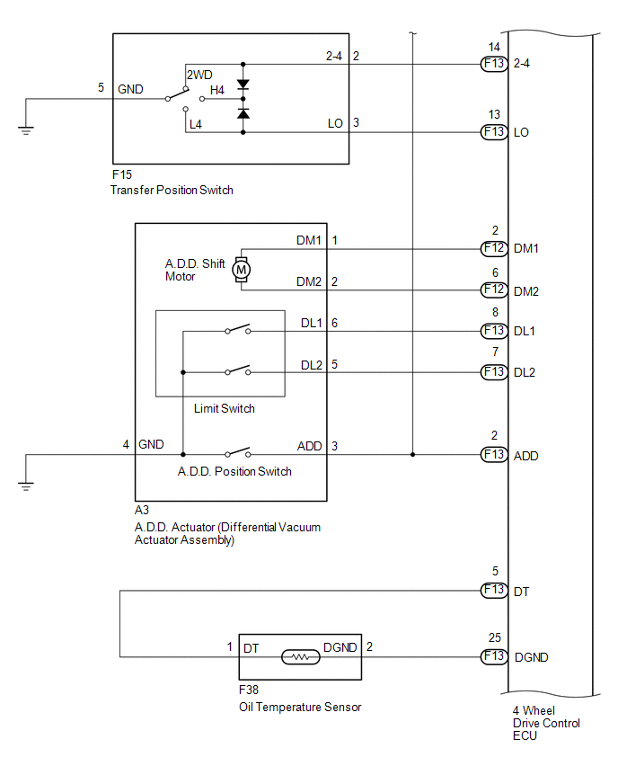
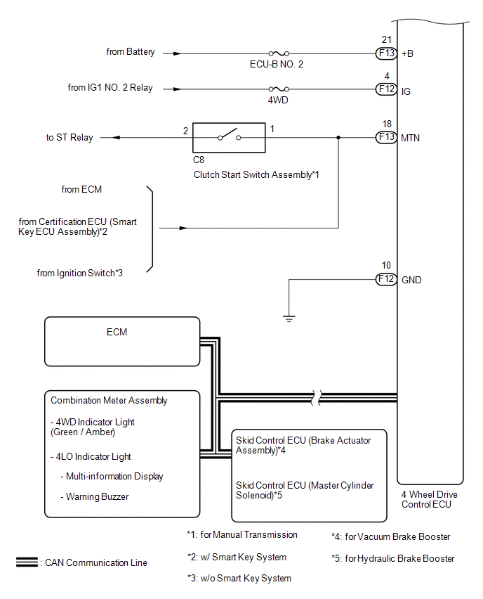
SYSTEM DIAGRAM
|
Transmitting ECU (Transmitter) |
Receiving ECU |
Signal |
Communication Method |
|---|---|---|---|
|
4 wheel drive control ECU |
Skid control ECU (Brake actuator assembly) |
|
CAN communication system |
|
Skid control ECU (Brake actuator assembly) |
4 wheel drive control ECU |
|
CAN communication system |
|
4 wheel drive control ECU |
ECM |
|
CAN communication system |
|
ECM |
4 wheel drive control ECU |
|
CAN communication system |
|
4 wheel drive control ECU |
Combination meter assembly |
|
CAN communication system |
 System Description
SYSTEM DESCRIPTION
1. DESCRIPTION
A part-time 2-speed VF2CM transfer uses a touch select 2-4 and high-low
system, enabling the driver to switch between 2WD, H4 and L4 modes by turning
...
 Diagnosis System
DIAGNOSIS SYSTEM
1. DESCRIPTION
The 4 wheel drive control ECU records DTCs when the ECU detects a malfunction
in the ECU itself or in system circuits.
The DTCs can be read through the DLC3 of the ...
Other materials:
Installation
INSTALLATION
PROCEDURE
1. INSTALL CHARCOAL CANISTER LEAK DETECTION PUMP SUB-ASSEMBLY
(a) Engage the 2 claws to install a new charcoal canister leak detection
pump sub-assembly to the charcoal canister assembly.
NOTICE:
Do not allow foreign matter such as grease, ...
Wireless Charger Power Source Circuit
DESCRIPTION
This is the power source circuit to operate the mobile wireless charger cradle
assembly.
WIRING DIAGRAM
CAUTION / NOTICE / HINT
NOTICE:
Inspect the fuses for circuits related to this system before performing the following
inspection procedure.
PROCEDURE
1.
...
IG Supply Voltage Low (C120B)
DESCRIPTION
DTC No.
Detection Item
DTC Detection Condition
Trouble Area
C120B
IG Supply Voltage Low
Master cylinder pressure sensor power supply voltage decrease occurs
or history of voltage decrease exists, and ...
