
Toyota Tacoma (2015-2018) Service Manual: Vsc Off Switch
Components
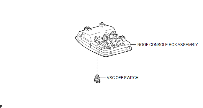
COMPONENTS
ILLUSTRATION
Inspection
INSPECTION
PROCEDURE
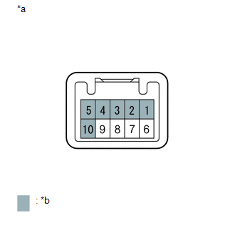
1. INSPECT VSC OFF SWITCH
(a) Check the resistance.
|
(1) Measure the resistance according to the value(s) in the table below. Text in Illustration
Standard Resistance:
If the value is not as specified, replace the VSC off switch. |
|
Removal
REMOVAL
PROCEDURE
1. REMOVE ROOF CONSOLE BOX ASSEMBLY
(See page .gif) )
)
2. REMOVE VSC OFF SWITCH
(a) Disconnect the VSC off switch connector.
|
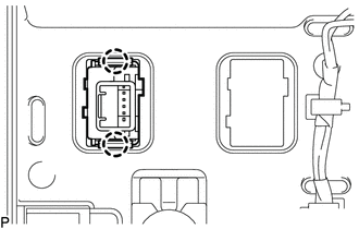
(b) Disengage the 2 claws and remove the VSC off switch from the roof console box assembly. |
|
Installation
INSTALLATION
PROCEDURE
1. INSTALL VSC OFF SWITCH
(a) Engage the 2 claws to install the VSC off switch into the roof console box assembly.
(b) Connect the VSC off switch connector.
2. INSTALL ROOF CONSOLE BOX ASSEMBLY
(See page .gif) )
)
 VSC OFF Switch Circuit
DESCRIPTION
The skid control ECU assembly is connected to the combination meter assembly
via CAN communication.
Pressing the VSC OFF switch turns off TRAC operation, and pressing and holding
thi ...
 Parking Brake
...
Other materials:
Removal
REMOVAL
PROCEDURE
1. PRECAUTION
NOTICE:
After turning the ignition switch off, waiting time may be required before disconnecting
the cable from the negative (-) battery terminal. Therefore, make sure to read the
disconnecting the cable from the negative (-) battery terminal notices before pr ...
Inspection
INSPECTION
PROCEDURE
1. INSPECT TIRES
(a) Check the tires for wear and proper inflation pressure.
Standard Cold Tire Inflation Pressure:
Tire Size
Front Wheel
kPa (kgf/cm2, psi)
Rear Wheel
kPa (kgf/cm2, psi)
Spare Wheel
kPa (kgf/cm2, psi)
...
Dtc Check / Clear
DTC CHECK / CLEAR
NOTICE:
When the diagnosis system is changed from normal mode to check mode or vice versa,
all DTCs and freeze frame data recorded in normal mode are cleared. Before changing
modes, always check and make a note of DTCs and freeze frame data.
HINT:
DTCs which are sto ...
