Toyota Tacoma (2015-2018) Service Manual: Short in Side Squib RH Circuit (B1820/55-B1823/55)
DESCRIPTION
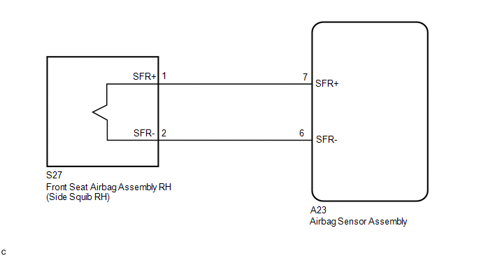
The side squib RH circuit consists of the airbag sensor assembly and the front seat airbag assembly RH.
The circuit signals the SRS to deploy when airbag deployment conditions are met.
These DTCs are set when a malfunction is detected in the side squib RH circuit.
|
DTC No. |
DTC Detecting Conditions |
Trouble Areas |
|---|---|---|
|
B1820/55 |
|
|
|
B1821/55 |
|
|
|
B1822/55 |
|
|
|
B1823/55 |
|
|
WIRING DIAGRAM
CAUTION / NOTICE / HINT
NOTICE:
After turning the ignition switch off, waiting time may be required before disconnecting
the cable from the negative (-) battery terminal. Therefore, make sure to read the
disconnecting the cable from the negative (-) battery terminal notices before proceeding
with work (See page .gif) ).
).
HINT:
- Perform the simulation method by selecting check mode (Signal Check)
using the Techstream (See page ).
- After selecting check mode (Signal Check), perform the simulation method
by wiggling each connector of the airbag system or driving the vehicle on
a city road or rough road (See page
).
PROCEDURE
|
1. |
CHECK DTC |
(a) Proceed to the appropriate step according to DTC readings.
(1) If using the Techstream (read the 5-digit DTCs):
Using the Techstream, check for DTCs (See page
).
|
Result |
Proceed to |
|---|---|
|
DTC B1820 is output. |
A |
|
DTC B1821 is output. |
B |
|
DTC B1822 is output. |
C |
|
DTC B1823 is output. |
D |
| B | .gif) |
GO TO STEP 3 |
| C | |
GO TO STEP 4 |
| D | |
GO TO STEP 5 |
|
.gif)
|
2. |
CHECK FLOOR WIRE (FOR SHORT) |
|
(a) Release the activation prevention mechanism built into connector
B (See page |
|
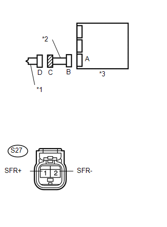
(b) Measure the resistance according to the value(s) in the table below.
Standard Resistance:
|
Tester Connection |
Condition |
Specified Condition |
|---|---|---|
|
S27-1 (SFR+) - S27-2 (SFR-) |
Always |
1 MΩ or Higher |
|
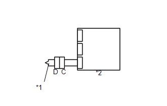
*1 |
Side Squib RH |
|
*2 |
Floor Wire |
|
*3 |
Airbag Sensor Assembly |
|
Result |
Proceed to |
|---|---|
|
NG |
A |
|
OK |
B |
| A | |
REPLACE FLOOR WIRE |
| B | |
GO TO STEP 6 |
|
3. |
CHECK FLOOR WIRE (FOR OPEN) |
|
(a) Measure the resistance according to the value(s) in the table below. Standard Resistance:
|
|
|
Result |
Proceed to |
|---|---|
|
NG |
A |
|
OK |
B |
| A | |
REPLACE FLOOR WIRE |
| B | |
GO TO STEP 7 |
|
4. |
CHECK FLOOR WIRE (TO GROUND) |
|
(a) Measure the resistance according to the value(s) in the table below. Standard Resistance:
|
|
|
Result |
Proceed to |
|---|---|
|
NG |
A |
|
OK |
B |
| A | |
REPLACE FLOOR WIRE |
| B | |
GO TO STEP 7 |
|
5. |
CHECK FLOOR WIRE (TO B+) |
|
(a) Connect the negative (-) terminal cable to the battery, and wait for at least 2 seconds. |
|
(b) Turn the ignition switch to ON.
(c) Measure the voltage according to the value(s) in the table below.
Standard Voltage:
|
Tester Connection |
Switch Condition |
Specified Condition |
|---|---|---|
|
S27-1 (SFR+) - Body ground |
Ignition switch ON |
Below 1 V |
|
S27-2 (SFR-) - Body ground |
Ignition switch ON |
Below 1 V |
|
*1 |
Side Squib RH |
|
*2 |
Floor Wire |
|
*3 |
Airbag Sensor Assembly |
|
Result |
Proceed to |
|---|---|
|
NG |
A |
|
OK |
B |
| A | |
REPLACE FLOOR WIRE |
| B | |
GO TO STEP 7 |
|
6. |
CHECK AIRBAG SENSOR ASSEMBLY |
|
(a) Connect the connectors to the airbag sensor assembly. |
|
(b) Connect the negative (-) terminal cable to the battery, and wait for at least 2 seconds.
(c) Turn the ignition switch to ON, and wait for at least 60 seconds.
(d) Clear any DTCs stored in the memory (See page
).
(e) Turn the ignition switch off.
(f) Turn the ignition switch to ON, and wait for at least 60 seconds.
(g) Check for DTCs (See page ).
OK:
DTC B1820 is not output.
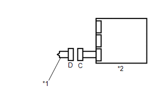
Text in Illustration|
*1 |
Side Squib RH |
|
*2 |
Airbag Sensor Assembly |
HINT:
DTCs other than B1820 may be output at this time, but they are not related to this check.
Result|
Result |
Proceed to |
|---|---|
|
NG |
A |
|
OK |
B |
| A | |
REPLACE AIRBAG SENSOR ASSEMBLY |
| B | |
GO TO STEP 8 |
|
7. |
CHECK AIRBAG SENSOR ASSEMBLY |
HINT:
If continuing from step 5, begin from (a). If continuing from any other step, begin from (c).
|
(a) Turn the ignition switch off. |
|
(b) Disconnect the negative (-) terminal cable from the battery, and wait for at least 90 seconds.
(c) Connect the connectors to the airbag sensor assembly.
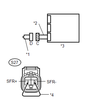
(d) Using a service wire, connect S27-1 (SFR+) and S27-2 (SFR-) of connector C.
NOTICE:
Do not forcibly insert the service wire into the terminals of the connector when connecting.
(e) Connect the negative (-) terminal cable to the battery, and wait for at least 2 seconds.
(f) Turn the ignition switch to ON, and wait for at least 60 seconds.
(g) Clear the DTCs stored in the memory (See page
).
(h) Turn the ignition switch off.
(i) Turn the ignition switch to ON, and wait for at least 60 seconds.
(j) Check for DTCs (See page ).
OK:
DTC B1821, B1822 and B1823 are not output.
Text in Illustration|
*1 |
Side Squib RH |
|
*2 |
Floor Wire |
|
*3 |
Airbag Sensor Assembly |
|
*4 |
Service Wire |
HINT:
DTCs other than B1821, B1822 or B1823 may be output at this time, but they are not related to this check.
| NG | |
REPLACE AIRBAG SENSOR ASSEMBLY |
|
|
8. |
CHECK FRONT SEAT AIRBAG ASSEMBLY RH |
HINT:
If continuing from step 9, begin from (c). If continuing from any other step, being from (a).
(a) Turn the ignition switch off.
(b) Disconnect the negative (-) terminal cable from the battery, and wait for at least 90 seconds.
(c) Disconnect the service wire from connector C.
(d) Connect the connector to the front seat airbag assembly RH (Side squib RH).
(e) Connect the negative (-) terminal cable to the battery, and wait for at least 2 seconds.
(f) Turn the ignition switch to ON, and wait for at least 60 seconds.
(g) Clear any DTCs stored in the memory (See page
).
(h) Turn the ignition switch off.
(i) Turn the ignition switch to ON, and wait for at least 60 seconds.
(j) Check for DTCs (See page ).
OK:
DTC B1820, B1821, B1822 and B1823 are not output.
Text in Illustration|
*1 |
Side Squib RH |
|
*2 |
Airbag Sensor Assembly |
HINT:
DTCs other than B1820, B1821, B1822 or B1823 may be output at this time, but they are not related to this check.
| OK | |
USE SIMULATION METHOD TO CHECK |
| NG | |
REPLACE FRONT SEAT AIRBAG ASSEMBLY RH |
 Short in Front Passenger Side Squib 2nd Step Circuit (B1815/54-B1818/54)
DESCRIPTION
The front passenger side squib 2nd step circuit consists of the airbag sensor
assembly and the instrument panel passenger without door airbag assembly.
The circuit signals the SRS to d ...
 Short in Side Squib LH Circuit (B1825/56-B1828/56)
DESCRIPTION
The side squib LH circuit consists of the airbag sensor assembly and the front
seat airbag assembly LH.
This circuit signals the SRS to deploy when airbag deployment conditions are
m ...
Other materials:
Inspection
INSPECTION
PROCEDURE
1. INSPECT CYLINDER HEAD SUB-ASSEMBLY
(a) Using a precision straightedge and feeler gauge, measure the warpage of the
contact surfaces where the cylinder head contacts the cylinder block sub-assembly
and manifolds.
Text in Illustration
*a
Intake S ...
Data List / Active Test
DATA LIST / ACTIVE TEST
READ DATA LIST
NOTICE:
In the table below, the values listed under "Normal Condition" are reference
values. Do not depend solely on these reference values when deciding whether a part
is faulty or not.
HINT:
Using the Techstream to read the Data List allows ...
Internal Control Module EEPROM Data Memory Failure (P062F44)
DESCRIPTION
The ECM monitors its internal operation and it will set this DTC when it detects
an internal malfunction.
DTC No.
DTC Detection Condition
Trouble Area
SAE
P062F44
ECM internal error (EEPROM)
ECM
...
