Toyota Tacoma (2015-2018) Service Manual: Inspection
INSPECTION
PROCEDURE
1. INSPECT CYLINDER HEAD SUB-ASSEMBLY
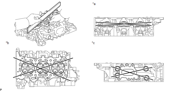
(a) Using a precision straightedge and feeler gauge, measure the warpage of the contact surfaces where the cylinder head contacts the cylinder block sub-assembly and manifolds.
 Text in Illustration
|
*a |
Intake Side |
*b |
Cylinder Block Side |
|
*c |
Exhaust Side |
- |
- |
Standard Warpage:
|
Item |
Specified Condition |
|---|---|
|
Cylinder Block Side |
0 to 0.05 mm (0 to 0.00197 in.) |
|
Exhaust Side |
0 to 0.08 mm (0 to 0.00315 in.) |
|
Intake Side |
0 to 0.08 mm (0 to 0.00315 in.) |
Maximum warpage:
0.10 mm (0.00394 in.)
If the warpage is more than the maximum, replace the cylinder head sub-assembly.
2. INSPECT CYLINDER HEAD FOR CRACKS
(a) Using a dye penetrant, check the intake ports, exhaust ports and cylinder surface for cracks.
If cracked, replace the cylinder head sub-assembly.
3. INSPECT INTAKE VALVE
(a) Using a micrometer, measure the diameter of the valve stem.
Standard valve stem diameter:
5.470 to 5.485 mm (0.215 to 0.216 in.)
If the valve stem is not as specified, check the oil clearance.
|
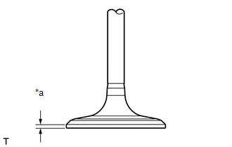
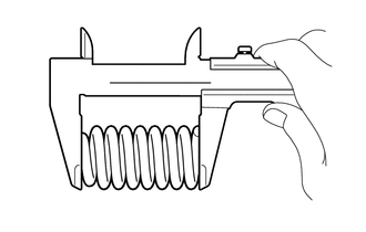
(b) Using a vernier caliper, measure the valve head margin thickness. Text in Illustration
Standard margin thickness: 1.0 mm (0.0394 in.) Minimum margin thickness: 0.5 mm (0.0197 in.) If the margin thickness is less than the minimum, replace the intake valve. |
|
(c) Using a vernier caliper, measure the valve overall length.
Standard overall length:
105.85 mm (4.17 in.)
Minimum overall length:
105.35 mm (4.15 in.)
If the overall length is less than the minimum, replace the intake valve.
4. INSPECT EXHAUST VALVE
(a) Using a micrometer, measure the diameter of the valve stem.
Standard valve stem diameter:
5.465 to 5.480 mm (0.215 to 0.216 in.)
If the valve stem is not as specified, check the oil clearance.
|
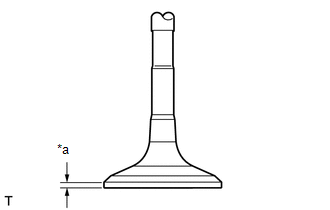
(b) Using a vernier caliper, measure the valve head margin thickness. Text in Illustration
Standard margin thickness: 1.0 mm (0.0394 in.) Minimum margin thickness: 0.5 mm (0.0197 in.) If the margin thickness is less than the minimum, replace the exhaust valve. |
|
(c) Using a vernier caliper, measure the valve overall length.
Standard overall length:
110.40 mm (4.35 in.)
Minimum overall length:
109.90 mm (4.33 in.)
If the overall length is less than the minimum, replace the exhaust valve.
5. INSPECT INTAKE VALVE SEAT
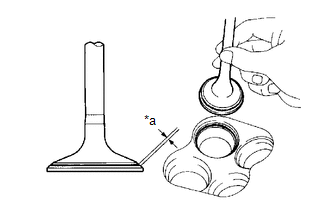
(a) Apply a light coat of Prussian blue to the valve face.
(b) Lightly press the valve face against the valve seat.
|
(c) Check the valve face and valve spring seat by using the following procedure: Text in Illustration
(1) If Prussian blue appears around the entire valve face, the valve face is circular. If not, replace the valve. (2) If Prussian blue appears around the entire valve seat, the guide and valve face are concentric. If not, resurface the valve spring seat. (3) Check that the valve spring seat contacts the middle of the valve face with the width between 1.1 to 1.5 mm (0.0433 to 0.0591 in.). |
|
6. INSPECT EXHAUST VALVE SEAT
(a) Apply a light coat of Prussian blue to the valve face.
(b) Lightly press the valve face against the valve spring seat.
|
(c) Check the valve face and valve spring seat by using the following procedure: Text in Illustration
(1) If Prussian blue appears around the entire valve face, the valve face is circular. If not, replace the valve. (2) If Prussian blue appears around the entire valve seat, the guide and valve face are concentric. If not, resurface the valve spring seat. (3) Check that the valve spring seat contacts the middle of the valve face with the width between 1.3 to 1.7 mm (0.0512 to 0.0669 in.). |
|
7. INSPECT INNER COMPRESSION SPRING
|
(a) Using a vernier caliper, measure the free length of the inner compression spring. Standard free length: 54.53 mm (2.147 in.) |
|
|
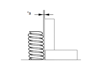
(b) Using a steel square, measure the deviation of the inner compression spring. Text in Illustration
Maximum deviation: 1.0 mm (0.0394 in.) Maximum angle (reference): 2° If the deviation is more than the maximum, replace the inner compression spring. |
|
8. INSPECT VALVE GUIDE BUSH OIL CLEARANCE
|
(a) Using a caliper gauge, measure the inside diameter of the valve guide bush. Standard bush inside diameter: 5.510 to 5.530 mm (0.217 to 0.218 in.) |
|
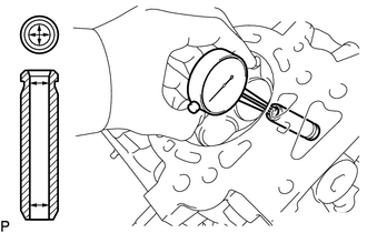
(b) Subtract the valve stem diameter measurement from the valve guide bush inside diameter measurement.
Standard Oil Clearance:
|
Item |
Specified Condition |
|---|---|
|
Intake |
0.025 to 0.060 mm (0.000984 to 0.00236 in.) |
|
Exhaust |
0.03 to 0.065 mm (0.00118 to 0.00256 in.) |
Maximum Oil Clearance:
|
Item |
Specified Condition |
|---|---|
|
Intake |
0.08 mm (0.00315 in.) |
|
Exhaust |
0.085 mm (0.00335 in.) |
If the clearance is more than the maximum, replace the valve and valve guide bush.
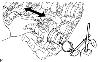
9. INSPECT CAMSHAFT THRUST CLEARANCE
(a) Inspect the bank 1 camshaft thrust clearance.
(1) Install the bank 1 camshafts (See page .gif) ).
).
|
(2) Using a dial indicator, measure the thrust clearance while moving the camshaft back and forth. Standard thrust clearance: 0.08 to 0.13 mm (0.00315 to 0.00512 in.) Maximum thrust clearance: 0.15 mm (0.00591 in.) If the thrust clearance is more than the maximum, replace the camshaft housing sub-assembly. If the thrust surface is damaged, replace the camshaft. |
|
(b) Inspect the bank 2 camshaft thrust clearance.
(1) Install the bank 2 camshafts (See page ).
(2) Using a dial indicator, measure the thrust clearance while moving the camshaft back and forth.
Standard thrust clearance:
0.08 to 0.13 mm (0.00315 to 0.00512 in.)
Maximum thrust clearance:
0.15 mm (0.00591 in.)
If the thrust clearance is more than the maximum, replace the camshaft housing sub-assembly. If the thrust surface is damaged, replace the camshaft.
 Disassembly
DISASSEMBLY
PROCEDURE
1. REMOVE INTAKE VALVE
(a) Using SST, compress the inner compression spring and remove the valve
spring retainer locks.
SST: 09202-70020
SST: 09202-00021
...
 Replacement
REPLACEMENT
PROCEDURE
1. REPLACE INTAKE VALVE GUIDE BUSH
(a) Heat the cylinder head to 80 to 100°C (176 to 212°F).
(b) Place the cylinder head on wooden blocks.
(c) Using SST and a h ...
Other materials:
Open in One Side of Bus 2 Branch Line
DESCRIPTION
When the CAN bus main lines are normal (no open, short to ground, short to +B
or short between lines) and there is an ECU or sensor on the "Communication Bus
Check" screen that is indicated as not communicating or whose connection status
on the "Communication Bus Ch ...
On-vehicle Inspection
ON-VEHICLE INSPECTION
PROCEDURE
1. INSPECT LOWER NO. 1 INSTRUMENT PANEL AIRBAG ASSEMBLY (for Vehicle not Involved
in Collision)
(a) Perform a diagnostic system check (See page
).
(b) With the lower No. 1 instrument panel airbag assembly ...
Operation Check
OPERATION CHECK
1. CHECK INTERMITTENT CONTROL FUNCTION (w/ Intermittent Time Adjustment Switch)
(a) Turn the ignition switch to ON.
(b) Turn the windshield wiper switch assembly to the INT position.
(c) Check that the intermittent operation interval can be adjusted from approximately
1.6 to 10 ...
