Toyota Tacoma (2015-2018) Service Manual: Short in Side Squib LH Circuit (B1825/56-B1828/56)
DESCRIPTION
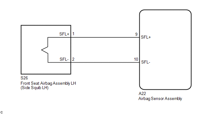
The side squib LH circuit consists of the airbag sensor assembly and the front seat airbag assembly LH.
This circuit signals the SRS to deploy when airbag deployment conditions are met.
These DTCs are set when a malfunction is detected in the side squib LH circuit.
|
DTC No. |
DTC Detecting Conditions |
Trouble Areas |
|---|---|---|
|
B1825/56 |
|
|
|
B1826/56 |
|
|
|
B1827/56 |
|
|
|
B1828/56 |
|
|
WIRING DIAGRAM
CAUTION / NOTICE / HINT
NOTICE:
After turning the ignition switch off, waiting time may be required before disconnecting
the cable from the negative (-) battery terminal. Therefore, make sure to read the
disconnecting the cable from the negative (-) battery terminal notices before proceeding
with work (See page .gif) ).
).
HINT:
- Perform the simulation method by selecting check mode (Signal Check)
using the Techstream (See page ).
- After selecting check mode (Signal Check), perform the simulation method
by wiggling each connector of the airbag system or driving the vehicle on
a city road or rough road (See page
).
PROCEDURE
|
1. |
CHECK DTC |
(a) Proceed to the appropriate step according to DTC readings.
(1) If using the Techstream (read the 5-digit DTCs):
Using the Techstream, check for DTCs (See page
).
|
Result |
Proceed to |
|---|---|
|
DTC B1825 is output. |
A |
|
DTC B1826 is output. |
B |
|
DTC B1827 is output. |
C |
|
DTC B1828 is output. |
D |
| B | .gif) |
GO TO STEP 3 |
| C | |
GO TO STEP 4 |
| D | |
GO TO STEP 5 |
|
.gif)
|
2. |
CHECK NO. 2 FLOOR WIRE (FOR SHORT) |
|
(a) Release the activation prevention mechanism built into connector
B (See page |
|
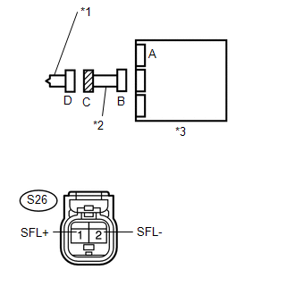
(b) Measure the resistance according to the value(s) in the table below.
Standard Resistance:
|
Tester Connection |
Condition |
Specified Condition |
|---|---|---|
|
S26-1 (SFL+) - S26-2 (SFL-) |
Always |
1 MΩ or Higher |
|
*1 |
Side Squib LH |
|
*2 |
No. 2 Floor Wire |
|
*3 |
Airbag Sensor Assembly |
|
Result |
Proceed to |
|---|---|
|
NG |
A |
|
OK |
B |
| A | |
REPLACE NO. 2 FLOOR WIRE |
| B | |
GO TO STEP 6 |
|
3. |
CHECK NO. 2 FLOOR WIRE (FOR OPEN) |
|
(a) Measure the resistance according to the value(s) in the table below. Standard Resistance:
|
|
|
Result |
Proceed to |
|---|---|
|
NG |
A |
|
OK |
B |
| A | |
REPLACE NO. 2 FLOOR WIRE |
| B | |
GO TO STEP 7 |
|
4. |
CHECK NO. 2 FLOOR WIRE (TO GROUND) |
|
(a) Measure the resistance according to the value(s) in the table below. Standard Resistance:
|
|
|
Result |
Proceed to |
|---|---|
|
NG |
A |
|
OK |
B |
| A | |
REPLACE NO. 2 FLOOR WIRE |
| B | |
GO TO STEP 7 |
|
5. |
CHECK NO. 2 FLOOR WIRE (TO B+) |
|
(a) Connect the negative (-) terminal cable to the battery, and wait for at least 2 seconds. |
|
(b) Turn the ignition switch to ON.
(c) Measure the voltage according to the value(s) in the table below.
Standard Voltage:
|
Tester Connection |
Switch Condition |
Specified Condition |
|---|---|---|
|
S26-1 (SFL+) - Body ground |
Ignition switch ON |
Below 1 V |
|
S26-2 (SFL-) - Body ground |
Ignition switch ON |
Below 1 V |
|
*1 |
Side Squib LH |
|
*2 |
No. 2 Floor Wire |
|
*3 |
Airbag Sensor Assembly |
|
Result |
Proceed to |
|---|---|
|
NG |
A |
|
OK |
B |
| A | |
REPLACE NO. 2 FLOOR WIRE |
| B | |
GO TO STEP 7 |
|
6. |
CHECK AIRBAG SENSOR ASSEMBLY |
|
(a) Connect the connectors to the airbag sensor assembly. |
|
(b) Connect the negative (-) terminal cable to the battery, and wait for at least 2 seconds.
(c) Turn the ignition switch to ON, and wait for at least 60 seconds.
(d) Clear any DTCs stored in the memory (See page
).
(e) Turn the ignition switch off.
(f) Turn the ignition switch to ON, and wait for at least 60 seconds.
(g) Check for DTCs (See page ).
OK:
DTC B1825 is not output.
Text in Illustration|
*1 |
Side Squib LH |
|
*2 |
Airbag Sensor Assembly |
HINT:
DTCs other than B1825 may be output at this time, but they are not related to this check.
Result|
Result |
Proceed to |
|---|---|
|
NG |
A |
|
OK |
B |
| A | |
REPLACE AIRBAG SENSOR ASSEMBLY |
| B | |
GO TO STEP 8 |
|
7. |
CHECK AIRBAG SENSOR ASSEMBLY |
HINT:
If continuing from step 5, begin from (a). If continuing from any other step, begin from (c).
|
(a) Turn the ignition switch off. |
|
(b) Disconnect the negative (-) terminal cable from the battery, and wait for at least 90 seconds.
(c) Connect the connectors to the airbag sensor assembly.
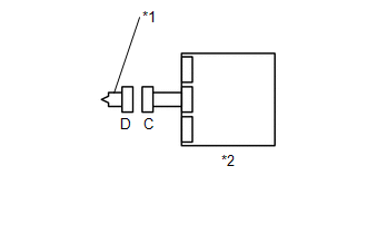
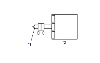
(d) Using a service wire, connect S26-1 (SFL+) and S26-2 (SFL-) of connector C.
NOTICE:
Do not forcibly insert the service wire into the terminals of the connector when connecting.
(e) Connect the negative (-) terminal cable to the battery, and wait for at least 2 seconds.
(f) Turn the ignition switch to ON, and wait for at least 60 seconds.
(g) Clear any DTCs stored in the memory (See page
).
(h) Turn the ignition switch off.
(i) Turn the ignition switch to ON, and wait for at least 60 seconds.
(j) Check for DTCs (See page ).
OK:
DTC B1826, B1827 and B1828 are not output.
Text in Illustration|
*1 |
Side Squib LH |
|
*2 |
No. 2 Floor Wire |
|
*3 |
Airbag Sensor Assembly |
|
*4 |
Service Wire |
HINT:
DTCs other than B1826, B1827 or B1828 may be output at this time, but they are not related to this check.
| NG | |
REPLACE AIRBAG SENSOR ASSEMBLY |
|
|
8. |
CHECK FRONT SEAT AIRBAG ASSEMBLY LH |
HINT:
If continuing from step 9, begin from (c). If continuing from any other step, being from (a).
(a) Turn the ignition switch off.
(b) Disconnect the negative (-) terminal cable from the battery, and wait for at least 90 seconds.
(c) Disconnect the service wire from connector C.
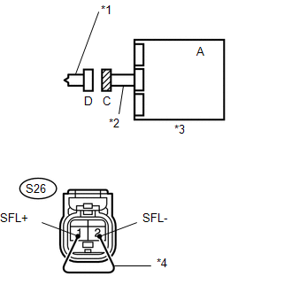
(d) Connect the connector to the front seat airbag assembly LH.
(e) Connect the negative (-) terminal cable to the battery, and wait for at least 2 seconds.
(f) Turn the ignition switch to ON, and wait for at least 60 seconds.
(g) Clear any DTCs stored in the memory (See page
).
(h) Turn the ignition switch off.
(i) Turn the ignition switch to ON, and wait for at least 60 seconds.
(j) Check for DTCs (See page ).
OK:
DTC B1825, B1826, B1827 and B1828 are not output.
Text in Illustration|
*1 |
Side Squib LH |
|
*2 |
Airbag Sensor Assembly |
HINT:
DTCs other than B1825, B1826, B1827 or B1828 may be output at this time, but they are not related to this check.
| OK | |
USE SIMULATION METHOD TO CHECK |
| NG | |
REPLACE FRONT SEAT AIRBAG ASSEMBLY LH |
 Short in Side Squib RH Circuit (B1820/55-B1823/55)
DESCRIPTION
The side squib RH circuit consists of the airbag sensor assembly and the front
seat airbag assembly RH.
The circuit signals the SRS to deploy when airbag deployment conditions are met. ...
 Short in Curtain Shield Squib RH Circuit (B1830/57-B1833/57)
DESCRIPTION
The front passenger side curtain shield squib circuit consists of the airbag
sensor assembly and the curtain shield airbag assembly RH.
The circuit signals the SRS to deploy when airba ...
Other materials:
Confirm Cellular Phone Functionality
PROCEDURE
1.
CHECK CUSTOMER'S CELLULAR PHONE COMPATIBILITY
(a) Check if the cellular phone is compatible (Refer to http://www.toyota.com/entune/).
Result
Result
Proceed to
Cellular phone is compatible
A
...
Removal
REMOVAL
PROCEDURE
1. REMOVE WATER INLET WITH THERMOSTAT SUB-ASSEMBLY
(See page )
2. REMOVE NO. 1 RADIATOR HOSE
3. REMOVE NO. 2 RADIATOR HOSE
4. DISCONNECT RADIATOR RESERVE TANK HOSE
5. SEPARATE TRANSMISSION OIL COOLER HOSE (for Automatic Transmission)
(a) Disengage the c ...
Components
COMPONENTS
ILLUSTRATION
*1
FRONT ARMREST BASE UPPER PANEL SUB-ASSEMBLY
*2
FRONT DOOR GLASS INNER WEATHERSTRIP
*3
FRONT DOOR INSIDE HANDLE BEZEL PLUG
*4
FRONT DOOR INSIDE HANDLE SUB-ASSEMBLY
...
