Toyota Tacoma (2015-2018) Service Manual: Short in Front Passenger Side Squib 2nd Step Circuit (B1815/54-B1818/54)
DESCRIPTION
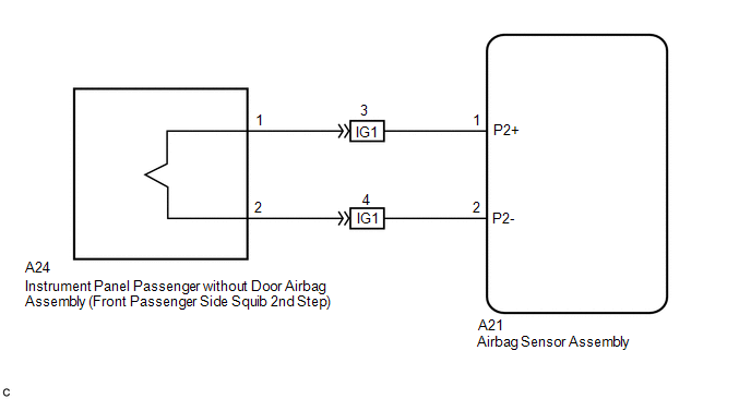
The front passenger side squib 2nd step circuit consists of the airbag sensor assembly and the instrument panel passenger without door airbag assembly.
The circuit signals the SRS to deploy when airbag deployment conditions are met.
These DTCs are set when a malfunction is detected in the front passenger side squib 2nd step circuit.
|
DTC No. |
DTC Detecting Conditions |
Trouble Areas |
|---|---|---|
|
B1815/54 |
|
|
|
B1816/54 |
|
|
|
B1817/54 |
|
|
|
B1818/54 |
|
|
WIRING DIAGRAM
CAUTION / NOTICE / HINT
NOTICE:
After turning the ignition switch off, waiting time may be required before disconnecting
the cable from the negative (-) battery terminal. Therefore, make sure to read the
disconnecting the cable from the negative (-) battery terminal notices before proceeding
with work (See page .gif) ).
).
HINT:
- Perform the simulation method by selecting check mode (Signal Check)
using the Techstream (See page ).
- After selecting check mode (Signal Check), perform the simulation method
by wiggling each connector of the airbag system or driving the vehicle on
a city road or rough road (See page
).
PROCEDURE
|
1. |
CHECK DTC OUTPUT |
(a) Proceed to the appropriate step according to the DTC readings.
(1) If using the Techstream (read the 5-digit DTCs): Using the Techstream, check
for DTCs (See page ).
|
Result |
Proceed to |
|---|---|
|
DTC B1815 is output. |
A |
|
DTC B1816 is output. |
B |
|
DTC B1817 is output. |
C |
|
DTC B1818 is output. |
D |
| B | .gif) |
GO TO STEP 7 |
| C | |
GO TO STEP 11 |
| D | |
GO TO STEP 15 |
|
.gif)
|
2. |
CHECK CONNECTOR |
(a) Turn the ignition switch off.
(b) Disconnect the negative (-) terminal cable from the battery, and wait for at least 90 seconds.
(c) Check that the instrument panel wire assembly connectors (on the instrument panel passenger without door airbag assembly side) are not damaged.
OK:
The lock button is not disengaged, and the claw of the lock is not deformed or damaged.
| NG | |
REPLACE INSTRUMENT PANEL WIRE ASSEMBLY |
|
|
3. |
CHECK CONNECTION OF CONNECTORS |
(a) Check that the connectors are properly connected to the airbag sensor assembly and the instrument panel wire assembly.
OK:
The connectors are properly connected.
| NG | |
CONNECT CONNECTORS |
|
|
4. |
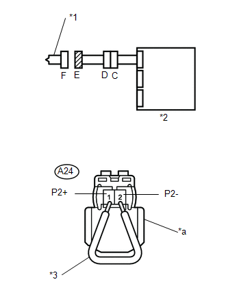
CHECK INSTRUMENT PANEL WIRE ASSEMBLY (FOR SHORT) |
|
(a) Disconnect the instrument panel wire assembly connectors from the instrument panel wire and instrument panel passenger without door airbag assembly. |
|
(b) Release the activation prevention mechanism built into connector D (See page
).
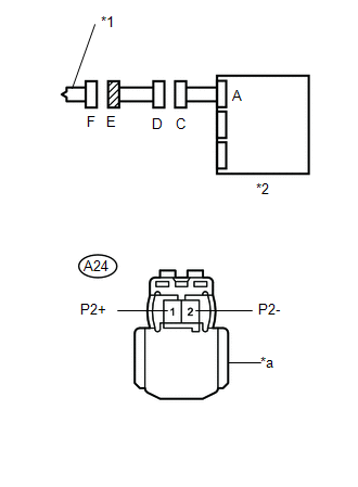
(c) Measure the resistance according to the value(s) in the table below.
Standard Resistance:
|
Tester Connection |
Condition |
Specified Condition |
|---|---|---|
|
A24-1 (P2+) - A24-2 (P2-) |
Always |
1 MΩ or Higher |
|
*1 |
Front Passenger Side Squib 2nd Step |
|
*2 |
Airbag Sensor Assembly |
|
*a |
Color: Black |
| NG | |
REPLACE INSTRUMENT PANEL WIRE ASSEMBLY |
|
|
5. |
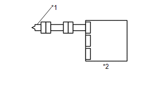
CHECK INSTRUMENT PANEL WIRE (FOR SHORT) |
|
(a) Disconnect the instrument panel wire connector from the airbag sensor assembly. |
|
(b) Release the activation prevention mechanism built into connector B (See page
).
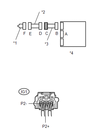
(c) Measure the resistance according to the value(s) in the table below.
Standard Resistance:
|
Tester Connection |
Condition |
Specified Condition |
|---|---|---|
|
IG1-3 (P2+) - IG1-4 (P2-) |
Always |
1 MΩ or Higher |
|
*1 |
Front Passenger Side Squib 2nd Step |
|
*2 |
Instrument Panel Wire Assembly |
|
*3 |
Instrument Panel Wire |
|
*4 |
Airbag Sensor Assembly |
| NG | |
REPLACE INSTRUMENT PANEL WIRE |
|
|
6. |
CHECK AIRBAG SENSOR ASSEMBLY |
|
(a) Connect the instrument panel wire connectors to the airbag sensor assembly and instrument panel wire assembly. |
|
(b) Connect the negative (-) terminal cable to the battery, and wait for at least 2 seconds.
(c) Turn the ignition switch to ON, and wait for at least 60 seconds.
(d) Clear any DTCs stored in the memory (See page
).
(e) Turn the ignition switch off.
(f) Turn the ignition switch to ON, and wait for at least 60 seconds.
(g) Check for DTCs (See page ).
OK:
DTC B1815 is not output.
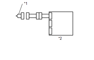
Text in Illustration|
*1 |
Front Passenger Side Squib 2nd Step |
|
*2 |
Airbag Sensor Assembly |
HINT:
DTCs other than B1815 may be output at this time, but they are not related to this check.
Result|
Result |
Proceed to |
|---|---|
|
NG |
A |
|
OK |
B |
| A | |
REPLACE AIRBAG SENSOR ASSEMBLY |
| B | |
GO TO STEP 20 |
|
7. |
CHECK CONNECTOR |
(a) Turn the ignition switch off.
(b) Disconnect the negative (-) terminal cable from the battery, and wait for at least 90 seconds.
(c) Check that the instrument panel wire assembly connectors (on the instrument panel passenger without door airbag assembly side) are not damaged.
OK:
The lock button is not disengaged, and the claw of the lock is not deformed or damaged.
| NG | |
REPLACE INSTRUMENT PANEL WIRE ASSEMBLY |
|
|
8. |
CHECK CONNECTION OF CONNECTORS |
(a) Check that the connectors are properly connected to the airbag sensor assembly and the instrument panel wire assembly.
OK:
The connectors are properly connected.
| NG | |
CONNECT CONNECTORS |
|
|
9. |
CHECK INSTRUMENT PANEL WIRE ASSEMBLY (FOR OPEN) |
|
(a) Disconnect the instrument panel wire assembly connectors from the instrument panel wire and horn button assembly. |
|
(b) Measure the resistance according to the value(s) in the table below.
Standard Resistance:
|
Tester Connection |
Condition |
Specified Condition |
|---|---|---|
|
A24-1 (P2+) - A24-2 (P2-) |
Always |
Below 1 Ω |
|
*1 |
Front Passenger Side Squib 2nd Step |
|
*2 |
Airbag Sensor Assembly |
|
*a |
Color: Black |
| NG | |
REPLACE INSTRUMENT PANEL WIRE ASSEMBLY |
|
|
10. |
CHECK INSTRUMENT PANEL WIRE (FOR OPEN) |
|
(a) Disconnect the instrument panel wire connector assembly from the airbag sensor assembly. |
|
(b) Measure the resistance according to the value(s) in the table below.
Standard Resistance:
|
Tester Connection |
Condition |
Specified Condition |
|---|---|---|
|
IG1-3 (P2+) - IG1-4 (P2-) |
Always |
Below 1 Ω |
|
*1 |
Front Passenger Side Squib 2nd Step |
|
*2 |
Instrument Panel Wire Assembly |
|
*3 |
Instrument Panel Wire |
|
*4 |
Airbag Sensor Assembly |
|
Result |
Proceed to |
|---|---|
|
NG |
A |
|
OK |
B |
| A | |
REPLACE INSTRUMENT PANEL WIRE |
| B | |
GO TO STEP 19 |
|
11. |
CHECK CONNECTOR |
(a) Turn the ignition switch off.
(b) Disconnect the negative (-) terminal cable from the battery, and wait for at least 90 seconds.
(c) Check that the instrument panel wire assembly connectors (on the instrument panel passenger without door airbag assembly side) are not damaged.
OK:
The lock button is not disengaged, and the claw of the lock is not deformed or damaged.
| NG | |
REPLACE INSTRUMENT PANEL WIRE ASSEMBLY |
|
|
12. |
CHECK CONNECTION OF CONNECTORS |
(a) Check that the connectors are properly connected to the airbag sensor assembly and the instrument panel wire assembly.
OK:
The connectors are properly connected.
| NG | |
CONNECT CONNECTORS |
|
|
13. |
CHECK INSTRUMENT PANEL WIRE ASSEMBLY (TO GROUND) |
|
(a) Disconnect the spiral cable with sensor sub-assembly connectors from the instrument panel wire and horn button assembly. |
|
(b) Measure the resistance according to the value(s) in the table below.
Standard Resistance:
|
Tester Connection |
Condition |
Specified Condition |
|---|---|---|
|
A24-1 (P2+) - Body ground |
Always |
1 MΩ or Higher |
|
A24-2 (P2-) - Body ground |
Always |
1 MΩ or Higher |
|
*1 |
Front Passenger Side Squib 2nd Step |
|
*2 |
Airbag Sensor Assembly |
|
*a |
Color: Black |
| NG | |
REPLACE INSTRUMENT PANEL WIRE ASSEMBLY |
|
|
14. |
CHECK INSTRUMENT PANEL WIRE (TO GROUND) |
|
(a) Disconnect the instrument panel wire connector from the airbag sensor assembly. |
|
(b) Measure the resistance according to the value(s) in the table below.
Standard Resistance:
|
Tester Connection |
Condition |
Specified Condition |
|---|---|---|
|
IG1-3 (P2+) - Body ground |
Always |
1 MΩ or Higher |
|
IG1-4 (P2-) - Body ground |
Always |
1 MΩ or Higher |
|
*1 |
Front Passenger Side Squib 2nd Step |
|
*2 |
Instrument Panel Wire Assembly |
|
*3 |
Instrument Panel Wire |
|
*4 |
Airbag Sensor Assembly |
|
Result |
Proceed to |
|---|---|
|
NG |
A |
|
OK |
B |
| A | |
REPLACE INSTRUMENT PANEL WIRE |
| B | |
GO TO STEP 19 |
|
15. |
CHECK CONNECTOR |
(a) Turn the ignition switch off.
(b) Disconnect the negative (-) terminal cable from the battery, and wait for at least 90 seconds.
(c) Check that the instrument panel wire assembly connectors (on the instrument panel passenger without door airbag assembly side) are not damaged.
OK:
The lock button is not disengaged, and the claw of the lock is not deformed or damaged.
| NG | |
REPLACE INSTRUMENT PANEL WIRE ASSEMBLY |
|
|
16. |
CHECK CONNECTION OF CONNECTORS |
(a) Check that the connectors are properly connected to the airbag sensor assembly and the instrument panel wire assembly.
OK:
The connectors are properly connected.
| NG | |
CONNECT CONNECTORS |
|
|
17. |
CHECK INSTRUMENT PANEL WIRE ASSEMBLY (TO B+) |
|
(a) Disconnect the instrument panel wire assembly connectors from the instrument panel wire and horn button assembly. |
|
(b) Connect the negative (-) terminal cable to the battery, and wait for at least 2 seconds.
(c) Turn the ignition switch to ON.
(d) Measure the voltage according to the value(s) in the table below.
Standard Voltage:
|
Tester Connection |
Switch Condition |
Specified Condition |
|---|---|---|
|
A24-1 (P2+) - Body ground |
Ignition switch ON |
Below 1 V |
|
A24-2 (P2-) - Body ground |
Ignition switch ON |
Below 1 V |
|
*1 |
Front Passenger Side Squib 2nd Step |
|
*2 |
Airbag Sensor Assembly |
|
*a |
Color: Black |
| NG | |
REPLACE INSTRUMENT PANEL WIRE ASSEMBLY |
|
|
18. |
CHECK INSTRUMENT PANEL WIRE (TO B+) |
|
(a) Turn the ignition switch off. |
|
(b) Disconnect the negative (-) terminal cable from the battery, and wait for at least 90 seconds.
(c) Disconnect the instrument panel wire connector from the airbag sensor assembly.
(d) Connect the negative (-) terminal cable to the battery, and wait for at least 2 seconds.
(e) Turn the ignition switch to ON.
(f) Measure the voltage according to the value(s) in the table below.
Standard Voltage:
|
Tester Connection |
Condition |
Specified Condition |
|---|---|---|
|
IG1-3 (P2+) - Body ground |
Always |
Below 1 V |
|
IG1-4 (P2-) - Body ground |
Always |
Below 1 V |
|
*1 |
Front Passenger Side Squib 2nd Step |
|
*2 |
Instrument Panel Wire Assembly |
|
*3 |
Instrument Panel Wire |
|
*4 |
Airbag Sensor Assembly |
| NG | |
REPLACE INSTRUMENT PANEL WIRE |
|
|
19. |
CHECK AIRBAG SENSOR ASSEMBLY |
HINT:
If continuing from step 14, begin from (a). If continuing from any other step, begin from (c).
(a) Turn the ignition switch off.
(b) Disconnect the negative (-) terminal cable from the battery, and wait for at least 90 seconds.
(c) Connect the connectors to the airbag sensor assembly.
(d) Using a service wire, connect A24-1 (P2+) and A24-2 (P2-) of connector E.
NOTICE:
- Twist the end of the service wire in order to insert it into the connector.
- Do not forcibly insert the twisted service wire into the terminals of the connector when connecting.
(e) Connect the negative (-) terminal cable to the battery, and wait for at least 2 seconds.
(f) Turn the ignition switch to ON, and wait for at least 60 seconds.
(g) Clear any DTCs stored in the memory (See page
).
(h) Turn the ignition switch off.
(i) Turn the ignition switch to ON, and wait for at least 60 seconds.
(j) Check for DTCs (See page ).
OK:
DTCs B1816, B1817 and B1818 are not output.
Text in Illustration|
*1 |
Front Passenger Side Squib 2nd Step |
|
*2 |
Airbag Sensor Assembly |
|
*3 |
Service Wire |
|
*a |
Color: Black |
HINT:
DTCs other than B1816, B1817 or B1818 may be output at this time, but they are not related to this check.
| NG | |
REPLACE AIRBAG SENSOR ASSEMBLY |
|
|
20. |
CHECK INSTRUMENT PANEL PASSENGER WITHOUT DOOR AIRBAG ASSEMBLY (FRONT PASSENGER SIDE SQUIB 2nd STEP) |
HINT:
If continuing from step 19, begin from (c). If continuing from any other step, being from (a).
(a) Turn the ignition switch off.
(b) Disconnect the negative (-) terminal cable from the battery, and wait for at least 90 seconds.
(c) Disconnect the service wire from connector C.
(d) Connect the connectors to the instrument panel passenger without door airbag assembly.
(e) Connect the negative (-) terminal cable to the battery, and wait for at least 2 seconds.
(f) Turn the ignition switch to ON, and wait for at least 60 seconds.
(g) Clear any DTCs stored in the memory (See page
).
(h) Turn the ignition switch off.
(i) Turn the ignition switch to ON, and wait for at least 60 seconds.
(j) Check for DTCs (See page ).
OK:
DTC B1815, B1816, B1817 and B1818 are not output.
Text in Illustration|
*1 |
Front Passenger Side Squib 2nd Step |
|
*2 |
Airbag Sensor Assembly |
HINT:
DTCs other than B1815, B1816, B1817 or B1818 may be output at this time, but they are not related to this check.
| OK | |
USE SIMULATION METHOD TO CHECK |
| NG | |
REPLACE INSTRUMENT PANEL PASSENGER WITHOUT DOOR AIRBAG ASSEMBLY |
 Vehicle Control History
VEHICLE CONTROL HISTORY
1. Function Overview
(a) The vehicle control history is a function that records control data (record
data) when triggered by specific vehicle behavior. When DTCs are not de ...
 Short in Side Squib RH Circuit (B1820/55-B1823/55)
DESCRIPTION
The side squib RH circuit consists of the airbag sensor assembly and the front
seat airbag assembly RH.
The circuit signals the SRS to deploy when airbag deployment conditions are met. ...
Other materials:
System Description
SYSTEM DESCRIPTION
1. POWER WINDOW CONTROL SYSTEM DESCRIPTION
(a) The power window control system controls the power window operation using
the power window regulator motors. The main controls of this system are the power
window regulator master switch assembly (mounted on the driver door), po ...
On-vehicle Inspection
ON-VEHICLE INSPECTION
PROCEDURE
1. INSPECT FLUID LEVEL IN RESERVOIR
(a) Check the fluid level.
If the brake fluid level is lower than the MIN line, check for leaks and inspect
the disc brake pads. If necessary, refill the reservoir with brake fluid to the
MAX line after repair or replaceme ...
Registration
REGISTRATION
PROCEDURE
1. DESCRIPTION OF CODE REGISTRATION
HINT:
Registering an ID code enables the entry and start function, wireless
door lock control function and engine immobiliser function to be operated.
Code registration is needed when the certification ECU (smart key E ...
