Toyota Tacoma (2015-2018) Service Manual: Short in Curtain Shield Squib RH Circuit (B1830/57-B1833/57)
DESCRIPTION
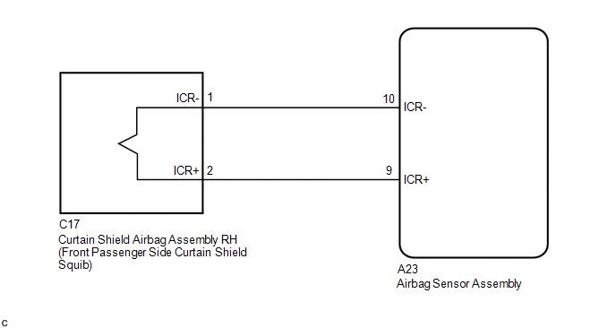
The front passenger side curtain shield squib circuit consists of the airbag sensor assembly and the curtain shield airbag assembly RH.
The circuit signals the SRS to deploy when airbag deployment conditions are met.
These DTCs are set when a malfunction is detected in the front passenger side curtain shield squib circuit.
|
DTC No. |
DTC Detections Conditions |
Trouble Areas |
|---|---|---|
|
B1830/57 |
|
|
|
B1831/57 |
|
|
|
B1832/57 |
|
|
|
B1833/57 |
|
|
WIRING DIAGRAM
CAUTION / NOTICE / HINT
NOTICE:
After turning the ignition switch off, waiting time may be required before disconnecting
the cable from the negative (-) battery terminal. Therefore, make sure to read the
disconnecting the cable from the negative (-) battery terminal notices before proceeding
with work (See page .gif) ).
).
HINT:
- Perform the simulation method by selecting check mode (Signal Check)
using the Techstream (See page ).
- After selecting check mode (Signal Check), perform the simulation method
by wiggling each connector of the airbag system or driving the vehicle on
a city road or rough road (See page
).
PROCEDURE
|
1. |
CHECK DTC |
(a) Proceed to the appropriate step according to DTC readings.
(1) If using the Techstream (read the 5-digit DTCs): Using the Techstream, check
for DTCs (See page ).
|
Result |
Proceed to |
|---|---|
|
B1830 is output. |
A |
|
B1831 is output. |
B |
|
B1832 is output. |
C |
|
B1833 is output. |
D |
| B | .gif) |
GO TO STEP 4 |
| C | |
GO TO STEP 5 |
| D | |
GO TO STEP 6 |
|
.gif)
|
2. |
CHECK CONNECTOR |
(a) Check that the floor wire connector (on the curtain shield airbag assembly RH side) is not damaged.
OK:
The lock button is not disengaged, and the claw of the lock is not deformed or damaged.
| NG | |
REPLACE FLOOR WIRE |
|
|
3. |
CHECK FLOOR WIRE (FOR SHORT) |
|
(a) Release the activation prevention mechanism built into connector
B (See page |
|
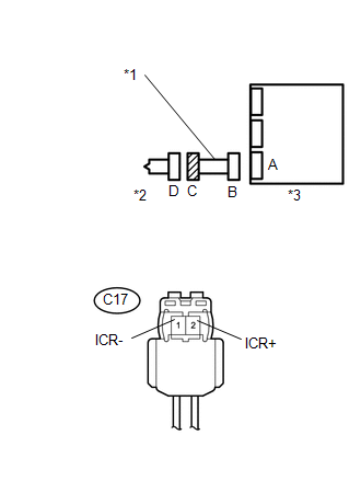
(b) Measure the resistance according to the value(s) in the table below.
Standard Resistance:
|
Tester Connection |
Condition |
Specified Condition |
|---|---|---|
|
C17-1 (ICR-) - C17-2 (ICR+) |
Always |
1 MΩ or higher |
|
*1 |
Floor Wire |
|
*2 |
Front Passenger Side Curtain Shield Squib |
|
*3 |
Airbag Sensor Assembly |
|
Result |
Proceed to |
|---|---|
|
NG |
A |
|
OK |
B |
| A | |
REPLACE FLOOR WIRE |
| B | |
GO TO STEP 7 |
|
4. |
CHECK FLOOR WIRE (FOR OPEN) |
|
(a) Measure the resistance according to the value(s) in the table below. Standard Resistance:
|
|
|
Result |
Proceed to |
|---|---|
|
NG |
A |
|
OK |
B |
| A | |
REPLACE FLOOR WIRE |
| B | |
GO TO STEP 8 |
|
5. |
CHECK FLOOR WIRE (TO GROUND) |
|
(a) Measure the resistance according to the value(s) in the table below. Standard Resistance:
|
|
|
Result |
Proceed to |
|---|---|
|
NG |
A |
|
OK |
B |
| A | |
REPLACE FLOOR WIRE |
| B | |
GO TO STEP 8 |
|
6. |
CHECK FLOOR WIRE (TO B+) |
|
(a) Connect the negative (-) terminal cable to the battery, and wait for at least 2 seconds. |
|
(b) Turn the ignition switch to ON.
(c) Measure the voltage according to the value(s) in the table below.
Standard Voltage:
|
Tester Connection |
Switch Condition |
Specified Condition |
|---|---|---|
|
C17-1 (ICR-) - Body ground |
Ignition switch ON |
Below 1 V |
|
C17-2 (ICR+) - Body ground |
Ignition switch ON |
Below 1 V |
|
*1 |
Floor Wire |
|
*2 |
Front Passenger Side Curtain Shield Squib |
|
*3 |
Airbag Sensor Assembly |
|
Result |
Proceed to |
|---|---|
|
NG |
A |
|
OK |
B |
| A | |
REPLACE FLOOR WIRE |
| B | |
GO TO STEP 8 |
|
7. |
CHECK AIRBAG SENSOR ASSEMBLY |
|
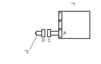
(a) Connect the connectors to the airbag sensor assembly. |
|
(b) Connect the negative (-) terminal cable to the battery, and wait for at least 2 seconds.
(c) Turn the ignition switch to ON, and wait for at least 60 seconds.
(d) Clear any DTCs stored in the memory (See page
).
(e) Turn the ignition switch off.
(f) Turn the ignition switch to ON, and wait for at least 60 seconds.
(g) Check for DTCs (See page ).
OK:
DTC B1830 is not output.
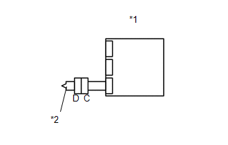
Text in Illustration|
*1 |
Airbag Sensor Assembly |
|
*2 |
Front Passenger Side Curtain Shield Squib |
HINT:
DTCs other than B1830 may be output at this time, but they are not related to this check.
Result|
Result |
Proceed to |
|---|---|
|
NG |
A |
|
OK |
B |
| A | |
REPLACE AIRBAG SENSOR ASSEMBLY |
| B | |
GO TO STEP 9 |
|
8. |
CHECK AIRBAG SENSOR ASSEMBLY |
HINT:
If continuing from step 6, begin from (a). If continuing from any other step, begin from (c).
|
(a) Turn the ignition switch off. |
|
(b) Disconnect the negative (-) terminal cable from the battery, and wait for at least 90 seconds.
(c) Connect the connectors to the airbag sensor assembly.
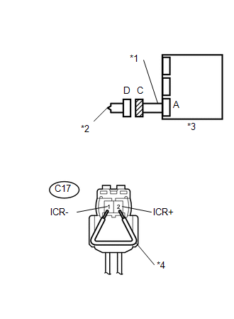
(d) Using a service wire, connect C17-1 (ICR-) and C17-2 (ICR+) of connector C.
NOTICE:
- Twist the end of the service wire in order to insert it into the connector.
- Do not forcibly insert the twisted service wire into the terminals of the connector when connecting.
(e) Connect the negative (-) terminal cable to the battery, and wait for at least 2 seconds.
(f) Turn the ignition switch to ON, and wait for at least 60 seconds.
(g) Clear any DTCs stored in the memory (See page
).
(h) Turn the ignition switch off.
(i) Turn the ignition switch to ON, and wait for at least 60 seconds.
(j) Check for DTCs (See page ).
OK:
DTC B1831, B1832 and B1833 are not output.
Text in Illustration|
*1 |
Floor Wire |
|
*2 |
Front Passenger Side Curtain Shield Squib |
|
*3 |
Airbag Sensor Assembly |
|
*4 |
Service Wire |
HINT:
DTCs other than B1831, B1832 or B1833 may be output at this time, but they are not related to this check.
| NG | |
REPLACE AIRBAG SENSOR ASSEMBLY |
|
|
9. |
CHECK CURTAIN SHIELD AIRBAG ASSEMBLY RH |
HINT:
If continuing from step 11, begin from (c). If continuing from any other step, being from (a).
|
(a) Turn the ignition switch off. |
|
(b) Disconnect the negative (-) terminal cable from the battery, and wait for at least 90 seconds.
(c) Disconnect the service wire from connector C.
(d) Connect the connector to the curtain shield airbag assembly RH.
(e) Connect the negative (-) terminal cable to the battery, and wait for at least 2 seconds.
(f) Turn the ignition switch to ON, and wait for at least 60 seconds.
(g) Clear any DTCs stored in the memory (See page
).
(h) Turn the ignition switch off.
(i) Turn the ignition switch to ON, and wait for at least 60 seconds.
(j) Check for DTCs (See page ).
OK:
DTC B1830, B1831, B1832 and B1833 are not output.
Text in Illustration|
*1 |
Airbag Sensor Assembly |
|
*2 |
Front Passenger Side Curtain Shield Squib |
HINT:
DTCs other than B1830, B1831, B1832 or B1833 may be output at this time, but they are not related to this check.
| OK | |
USE SIMULATION METHOD TO CHECK |
| NG | |
REPLACE CURTAIN SHIELD AIRBAG ASSEMBLY RH |
 Short in Side Squib LH Circuit (B1825/56-B1828/56)
DESCRIPTION
The side squib LH circuit consists of the airbag sensor assembly and the front
seat airbag assembly LH.
This circuit signals the SRS to deploy when airbag deployment conditions are
m ...
 Short in Curtain Shield Squib LH Circuit (B1835/58-B1838/58)
DESCRIPTION
The driver side curtain shield squib circuit consists of the airbag sensor assembly
and the curtain shield airbag assembly LH.
The circuit signals the SRS to deploy when airbag deploym ...
Other materials:
Driver Side Seat Heater does not Operate
DESCRIPTION
When the seat heater switch on the air conditioning control assembly is operated,
the air conditioning amplifier assembly receives the signal. The air conditioning
amplifier assembly receives the signal and operates the front seat heater.
WIRING DIAGRAM
CAUTION / NOTICE / HINT
...
Listening to a USB memory device
Connecting a USB memory device enables you to enjoy music from the vehicle
speakers.
Select “USB” on the “Select Audio Source” screen.
Connecting a USB memory device
Audio control screen
1. “Select Audio Source” screen appears
2. Displaying the folder list
3. Random playback
4 ...
Installation
INSTALLATION
PROCEDURE
1. INSTALL TRANSMISSION CASE GASKET
(a) Install 2 new transmission case gaskets to the automatic transmission case
sub-assembly.
2. INSTALL MANUAL VALVE
(a) Coat the manual valve with ATF and install it to the transmission valve body
assembly.
3. INSTALL TRANSMISSION ...
