Toyota Tacoma (2015-2018) Service Manual: Removal
REMOVAL
PROCEDURE
1. DRAIN DIFFERENTIAL OIL
2. REMOVE PROPELLER WITH CENTER BEARING SHAFT ASSEMBLY (for 2WD)
.gif)
3. REMOVE PROPELLER WITH CENTER BEARING SHAFT ASSEMBLY (for 4WD)
4. REMOVE REAR DRIVE PINION NUT
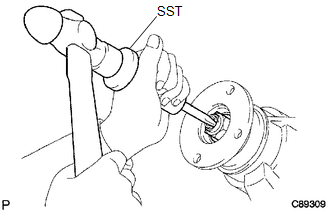
(a) Using SST and a hammer, unstake the nut.
SST: 09930-00010
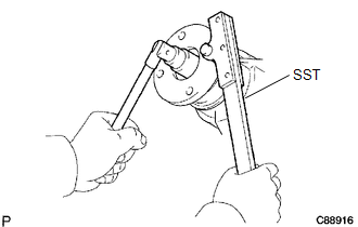
(b) for BD20:
|
(1) Using SST to hold the companion flange, remove the nut. SST: 09330-00021 |
|
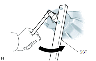
(c) for BD22:
|
(1) Using SST to hold the companion flange, remove the nut. SST: 09330-00021 |
|
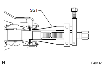
5. REMOVE REAR DRIVE PINION COMPANION FLANGE SUB-ASSEMBLY REAR
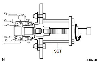
(a) Using SST, remove the companion flange.
SST: 09950-30012
09951-03010
09953-03010
09954-03010
09955-03030
09956-03030
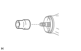
6. REMOVE REAR DIFFERENTIAL CARRIER OIL SEAL
(a) Using SST, remove the oil seal.
SST: 09308-10010
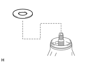
7. REMOVE REAR DIFFERENTIAL DRIVE PINION OIL SLINGER
|
(a) Remove the rear differential drive pinion oil slinger from the differential drive pinion. |
|
8. REMOVE REAR DRIVE PINION FRONT TAPERED ROLLER BEARING
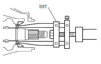
(a) Using SST, remove the front bearing.
SST: 09556-22010
(b) Using SST, remove the front bearing outer race.
SST: 09308-00010
9. REMOVE DIFFERENTIAL OIL STORAGE RING
(a) Using a screwdriver and hammer, tap out the differential oil storage ring.
10. REMOVE REAR DIFFERENTIAL DRIVE PINION BEARING SPACER
|
(a) Remove the front differential drive pinion bearing spacer from the differential drive pinion. |
|

 Installation
INSTALLATION
PROCEDURE
1. INSTALL REAR DIFFERENTIAL DRIVE PINION BEARING SPACER
(a) Install a new front differential drive pinion bearing spacer.
HINT:
Make sure the front differential drive pini ...
Other materials:
Removal
REMOVAL
PROCEDURE
1. REMOVE FUEL TANK ASSEMBLY
Click here
2. DISCONNECT FUEL TANK MAIN TUBE SUB-ASSEMBLY
Click here
3. REMOVE FUEL PUMP GAUGE RETAINER
NOTICE:
Before performing these procedures, first cover the connectors and tube joints
of the fuel suction tube with pump and gauge ass ...
Disassembly
DISASSEMBLY
PROCEDURE
1. REMOVE CONSOLE COMPARTMENT DOOR CUSHION
HINT:
Use the same procedure as for the opposite side.
(a) Disengage the claw to remove the console compartment door cushion.
2. REMOVE CONSOLE COMPARTMENT DOOR SUB-ASSEMBLY
...
Terminals Of Ecu
TERMINALS OF ECU
1. CHECK DRIVER SIDE JUNCTION BLOCK AND MAIN BODY ECU (MULTIPLEX NETWORK BODY
ECU)
(a) Disconnect the MB main body ECU (multiplex network body ECU) connectors.
(b) Measure the voltage and resistance according to the value(s) in the table
below.
HINT:
Measure the values on ...
