Toyota Tacoma (2015-2018) Service Manual: Diagnosis System
DIAGNOSIS SYSTEM
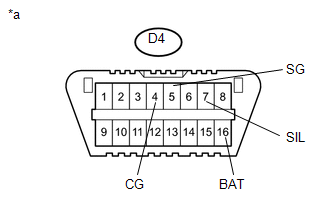
1. CHECK DLC3
(a) The vehicle ECUs use ISO 15765-4 communication protocol. The terminal arrangement of the DLC3 complies with ISO 15031-3 and matches the ISO 15765-4 format.
|
Terminals No. (Symbols) |
Terminal Description |
Condition |
Specified Condition |
|---|---|---|---|
|
D4-7 (SIL) - D4-5 (SG) |
Bus + line |
During transmission |
Pulse generation |
|
D4-4 (CG) - Body ground |
Chassis ground |
Always |
Below 1 Ω |
|
D4-16 (BAT) - Body ground |
Battery positive |
Always |
11 to 14 V |
|
*a |
DLC3 |
HINT:
If the display shows a communication error message when connecting the cable of the Techstream to the DLC3, turning the ignition switch to ON and operating the Techstream, there is a problem on the vehicle side or tool side.
- If communication is normal when the tool is connected to another vehicle, inspect the DLC3 on the original vehicle.
- If communication is still not possible when the tool is connected to another vehicle, the problem is probably in the tool itself. Consult the Service Department listed in the tool's instruction manual.
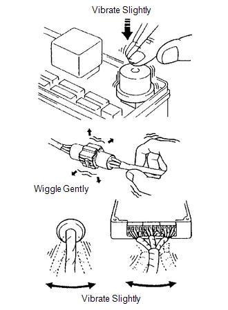
2. SYMPTOM SIMULATION
HINT:
The most difficult case in troubleshooting is when no symptoms occur. In such cases, a thorough customer problem analysis must be carried out. Then the same or similar conditions and environment in which the problem occurred in the customer's vehicle should be simulated. No matter how experienced or skilled a technician may be, if the technician proceeds to troubleshoot without confirming the problem symptoms, the technician will likely overlook something important and make a wrong guess at some points in the repair operation.
This leads to a standstill in troubleshooting.
(a) Vibration method: When vibration seems to be the major cause.
HINT:
Perform the simulation method only during the primary check period (for approximately 6 seconds after the ignition switch is turned to ON).
(1) Slightly vibrate the part of the sensor considered to be the problem cause with your fingers and check whether the malfunction occurs.
HINT:
Shaking the relays too strongly may result in open relays.
(2) Slightly shake the connector vertically and horizontally.
(3) Slightly shake the wire harness vertically and horizontally.
The connector joint and fulcrum of the vibration are the major areas to be checked thoroughly.
3. FUNCTION OF SRS WARNING LIGHT
(a) Primary check.
(1) Turn the ignition switch off. Wait for at least 2 seconds and then turn the ignition switch to ON. The SRS warning light comes on for approximately 6 seconds and the diagnosis of the airbag system (including the seat belt pretensioners) is performed.
HINT:
If trouble is detected during the primary check, the SRS warning light remains on even after the primary check period (for approximately 6 seconds) has elapsed.
(b) Constant check.
(1) After the primary check, the airbag sensor assembly constantly monitors the airbag system for trouble.
HINT:
If trouble is detected during the constant check, the airbag sensor assembly functions as follows:
- The SRS warning light comes on.
- The SRS warning light goes off, and then comes on. This blinking pattern indicates a source voltage drop. The SRS warning light goes off 10 seconds after the source voltage returns to normal.
(c) Review.
(1) When the airbag system is normal:
The SRS warning light comes on only during the primary check period (for approximately 6 seconds after the ignition switch is turned to ON).
(2) When the airbag system has trouble:
- The SRS warning light remains on even after the primary check period has elapsed.
- The SRS warning light goes off after the primary check, but comes on again during the constant check.
- The SRS warning light does not come on when turning the ignition switch from off to ON.
HINT:
The airbag sensor assembly keeps the SRS warning light on if the airbag has been deployed.
4. SRS WARNING LIGHT CHECK
(a) Turn the ignition switch to ON, and check that the SRS warning light comes on for approximately 6 seconds (primary check).
(b) Check that the SRS warning light goes off approximately 6 seconds after the ignition switch is turned ON (constant check).
HINT:
When any of the following symptoms occur, refer to the "Problem Symptoms Table"
(See page .gif) ).
).
- The SRS warning light comes on occasionally, after the primary check period has elapsed.
- The SRS warning light comes on, but a DTC is not output.
- The ignition switch is turned from off to ON, but the SRS warning light does not come on.
5. PASSENGER AIRBAG ON/OFF INDICATOR CHECK
(a) Turn the ignition switch to ON.
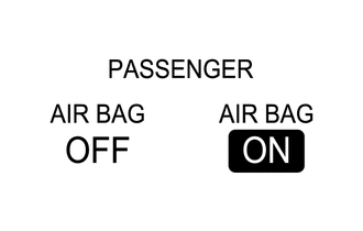
(b) Check that the passenger airbag ON/OFF indicator (ON and OFF) comes on for approximately 4 seconds, then turns off for approximately 2 seconds.
HINT:
Refer to the table in step 4 regarding the passenger airbag ON/OFF indicator when the ignition switch is turned to ON and approximately 6 seconds have passed.
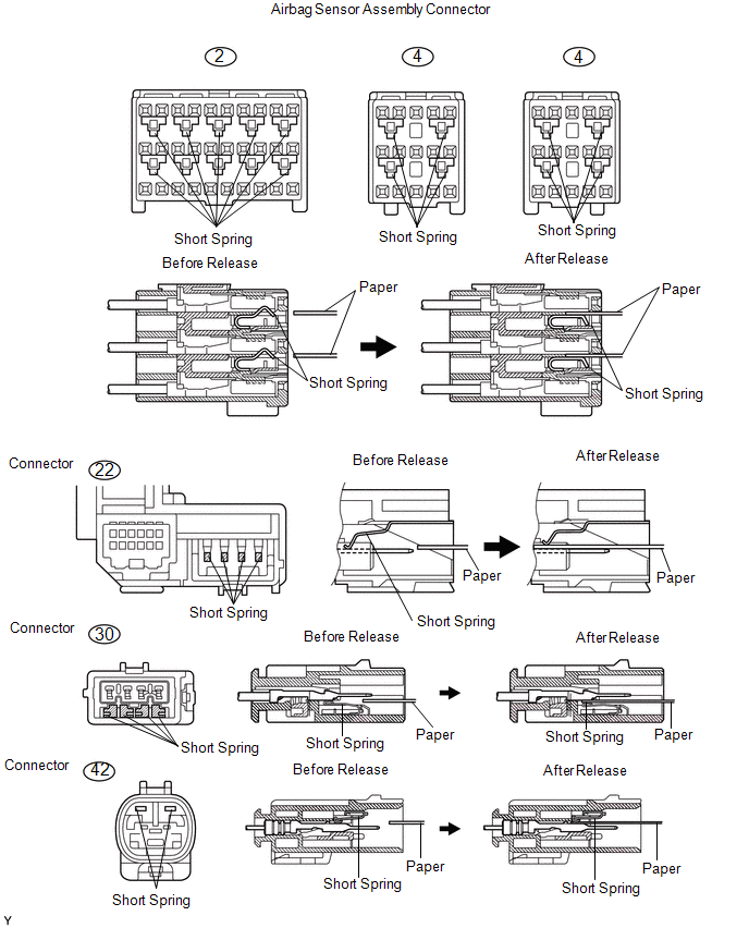
6. RELEASE METHOD OF ACTIVATION PREVENTION MECHANISM
(a) The activation prevention mechanism is built into the connector for the squib circuit of the SRS. As explained in the troubleshooting section, insert a piece of paper that is the same thickness as the male terminal between the terminal and the short spring to release it (refer to the illustrations on the next 3 pages).
CAUTION:
Never release the activation prevention mechanism on the squib connector even when inspecting with the squib disconnected.
NOTICE:
- Do not release the activation prevention mechanism unless specially directed by the troubleshooting procedure.
- To prevent the terminal and the short spring from being damaged, always use a piece of paper of the same thickness as the male terminal.
 Check Mode Procedure
CHECK MODE PROCEDURE
1. Check Mode (Signal Check): DTC CHECK
(a) Connect the Techstream to the DLC3.
(b) Turn the ignition switch to ON and turn the Techstream on.
(c) Select the Signal Check on t ...
 Dtc Check / Clear
DTC CHECK / CLEAR
1. SUPPLEMENTAL RESTRAINT SYSTEM DTC CHECK (USING SST CHECK WIRE)
(a) Check the DTCs (Present DTCs).
(1) Turn the ignition switch to ON, and wait for approximately 60 seconds.
...
Other materials:
Entune Audio
Operations such as listening to audio, using the hands-free phone, confirming
vehicle information and changing multimedia system settings are started by using
the following buttons.
Multimedia system operation buttons
button
Press this button to access the Bluetooth® hands-free system.
...
No Answer-Back
DESCRIPTION
In some cases, wireless door lock control functions are normal but the hazard
warning light and/or wireless door lock buzzer answer-back function(s) does not
operate. In such cases, hazard warning light and wireless door lock buzzer signal
outputs from the main body ECU (multiplex ...
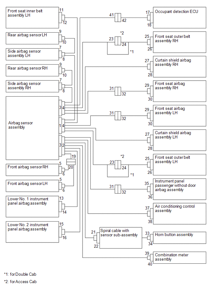
System Diagram
SYSTEM DIAGRAM
Communication Table
Sender
Receiver
Signal
Line
*1: for Vacuum Brake Booster
*2: for Hydraulic Brake Booster
Millimeter Wave Radar Sensor Assembly
Forward Recognition Camera
...
