Toyota Tacoma (2015-2018) Service Manual: Short in Curtain Shield Squib LH Circuit (B1835/58-B1838/58)
DESCRIPTION
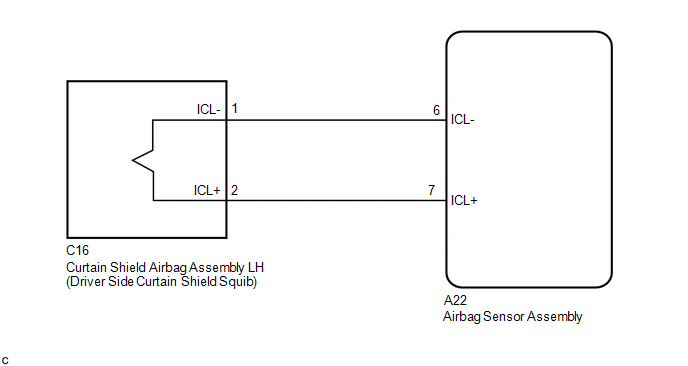
The driver side curtain shield squib circuit consists of the airbag sensor assembly and the curtain shield airbag assembly LH.
The circuit signals the SRS to deploy when airbag deployment conditions are met.
These DTCs are set when a malfunction is detected in the driver side curtain shield squib circuit.
|
DTC No. |
DTC Detecting Conditions |
Trouble Areas |
|---|---|---|
|
B1835/58 |
|
|
|
B1836/58 |
|
|
|
B1837/58 |
|
|
|
B1838/58 |
|
|
WIRING DIAGRAM
CAUTION / NOTICE / HINT
NOTICE:
After turning the ignition switch off, waiting time may be required before disconnecting
the cable from the negative (-) battery terminal. Therefore, make sure to read the
disconnecting the cable from the negative (-) battery terminal notices before proceeding
with work (See page .gif) ).
).
HINT:
- Perform the simulation method by selecting check mode (Signal Check)
using the Techstream (See page ).
- After selecting check mode (Signal Check), perform the simulation method
by wiggling each connector of the airbag system or driving the vehicle on
a city road or rough road (See page
).
PROCEDURE
|
1. |
CHECK DTC |
(a) Proceed to next step according to DTC readings.
(1) If using the Techstream (read the 5-digit DTCs):
Using the Techstream, check for DTCs (See page
).
|
Result |
Proceed to |
|---|---|
|
DTC B1835 is output. |
A |
|
DTC B1836 is output. |
B |
|
DTC B1837 is output. |
C |
|
DTC B1838 is output. |
D |
| B | .gif) |
GO TO STEP 4 |
| C | |
GO TO STEP 5 |
| D | |
GO TO STEP 6 |
|
.gif)
|
2. |
CHECK CONNECTOR |
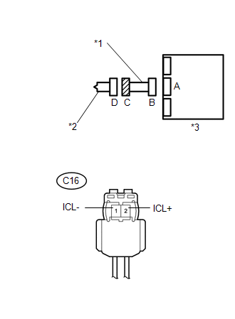
(a) Check that the floor wire connector (on the curtain shield airbag assembly LH side) is not damaged.
OK:
The lock button is not disengaged, and the claw of the lock is not deformed or damaged.
| NG | |
REPLACE NO. 2 FLOOR WIRE |
|
|
3. |
CHECK NO. 2 FLOOR WIRE (FOR SHORT) |
|
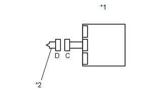
(a) Release the activation prevention mechanism built into connector
B (See page |
|
(b) Measure the resistance according to the value(s) in the table below.
Standard Resistance:
|
Tester Connection |
Condition |
Specified Condition |
|---|---|---|
|
C16-1 (ICL-) - C16-2 (ICL+) |
Always |
1 MΩ or Higher |
|
*1 |
No. 2 Floor Wire |
|
*2 |
Driver Side Curtain Shield Squib |
|
*3 |
Airbag Sensor Assembly |
|
Result |
Proceed to |
|---|---|
|
NG |
A |
|
OK |
B |
| A | |
REPLACE NO. 2 FLOOR WIRE |
| B | |
GO TO STEP 7 |
|
4. |
CHECK NO. 2 FLOOR WIRE (FOR OPEN) |
|
(a) Measure the resistance according to the value(s) in the table below. Standard Resistance:
|
|
|
Result |
Proceed to |
|---|---|
|
NG |
A |
|
OK |
B |
| A | |
REPLACE NO. 2 FLOOR WIRE |
| B | |
GO TO STEP 8 |
|
5. |
CHECK NO. 2 FLOOR WIRE (TO GROUND) |
|
(a) Measure the resistance according to the value(s) in the table below. Standard Resistance:
|
|
|
Result |
Proceed to |
|---|---|
|
NG |
A |
|
OK |
B |
| A | |
REPLACE NO. 2 FLOOR WIRE |
| B | |
GO TO STEP 8 |
|
6. |
CHECK NO. 2 FLOOR WIRE (TO B+) |
|
(a) Connect the negative (-) terminal cable to the battery, and wait for at least 2 seconds. |
|
(b) Turn the ignition switch to ON.
(c) Measure the voltage according to the value(s) in the table below.
Standard Voltage:
|
Tester Connection |
Switch Condition |
Specified Condition |
|---|---|---|
|
C16-1 (ICL-) - Body ground |
Ignition switch ON |
Below 1 V |
|
C16-2 (ICL+) - Body ground |
Ignition switch ON |
Below 1 V |
|
*1 |
No. 2 Floor Wire |
|
*2 |
Driver Side Curtain Shield Squib |
|
*3 |
Airbag Sensor Assembly |
|
Result |
Proceed to |
|---|---|
|
NG |
A |
|
OK |
B |
| A | |
REPLACE NO. 2 FLOOR WIRE |
| B | |
GO TO STEP 8 |
|
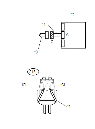
7. |
CHECK AIRBAG SENSOR ASSEMBLY |
|
(a) Connect the connectors to the airbag sensor assembly. |
|
(b) Connect the negative (-) terminal cable to the battery, and wait for at least 2 seconds.
(c) Turn the ignition switch to ON, and wait for at least 60 seconds.
(d) Clear any DTCs stored in the memory (See page
).
(e) Turn the ignition switch off.
(f) Turn the ignition switch to ON, and wait for at least 60 seconds.
(g) Check for DTCs (See page ).
OK:
DTC B1835 is not output.
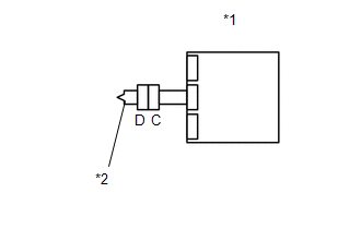
Text in Illustration|
*1 |
Airbag Sensor Assembly |
|
*2 |
Driver Side Curtain Shield Squib |
HINT:
DTCs other than B1835 may be output at this time, but they are not related to this check.
Result|
Result |
Proceed to |
|---|---|
|
NG |
A |
|
OK |
B |
| A | |
REPLACE AIRBAG SENSOR ASSEMBLY |
| B | |
GO TO STEP 9 |
|
8. |
CHECK AIRBAG SENSOR ASSEMBLY |
HINT:
If continuing from step 6, begin from (a). If continuing from any other step, begin from (c).
|
(a) Turn the ignition switch off. |
|
(b) Disconnect the negative (-) terminal cable from the battery, and wait for at least 90 seconds.
(c) Connect the connector to the airbag sensor assembly.
(d) Using a service wire, connect C16-1 (ICL-) and C16-2 (ICL+) of connector C.
NOTICE:
- Twist the end of the service wire in order to insert it into the connector.
- Do not forcibly insert the twisted service wire into the terminals of the connector when connecting.
(e) Connect the negative (-) terminal cable to the battery, and wait for at least 2 seconds.
(f) Turn the ignition switch to ON, and wait for at least 60 seconds.
(g) Clear any DTCs stored in the memory (See page
).
(h) Turn the ignition switch off.
(i) Turn the ignition switch to ON, and wait for at least 60 seconds.
(j) Check for DTCs (See page ).
OK:
DTC B1836, B1837 and B1838 are not output.
Text in Illustration|
*1 |
No. 2 Floor Wire |
|
*2 |
Airbag Sensor Assembly |
|
*3 |
Driver Side Curtain Shield Squib |
|
*4 |
Service Wire |
HINT:
DTCs other than B1836, B1837 or B1838 may be output at this time, but they are not related to this check.
| NG | |
REPLACE AIRBAG SENSOR ASSEMBLY |
|
|
9. |
CHECK CURTAIN SHIELD AIRBAG ASSEMBLY LH (DRIVER SIDE CURTAIN SHIELD SQUIB) |
HINT:
If continuing from step 11, begin from (c). If continuing from any other step, being from (a).
|
(a) Turn the ignition switch off. |
|
(b) Disconnect the negative (-) terminal cable from the battery, and wait for at least 90 seconds.
(c) Disconnect the service wire from connector C.
(d) Connect the connector to the curtain shield airbag assembly LH.
(e) Connect the negative (-) terminal cable to the battery, and wait for at least 2 seconds.
(f) Turn the ignition switch to ON, and wait for at least 60 seconds.
(g) Clear any DTCs stored in the memory (See page
).
(h) Turn the ignition switch off.
(i) Turn the ignition switch to ON, and wait for at least 60 seconds.
(j) Check for DTCs (See page ).
OK:
DTC B1835, B1836, B1837 and B1838 are not output.
Text in Illustration|
*1 |
Airbag Sensor Assembly |
|
*2 |
Driver Side Curtain Shield Squib |
HINT:
DTCs other than B1835, B1836, B1837 or B1838 may be output at this time, but they are not related to this check.
| OK | |
USE SIMULATION METHOD TO CHECK |
| NG | |
REPLACE CURTAIN SHIELD AIRBAG ASSEMBLY LH |
 Short in Curtain Shield Squib RH Circuit (B1830/57-B1833/57)
DESCRIPTION
The front passenger side curtain shield squib circuit consists of the airbag
sensor assembly and the curtain shield airbag assembly RH.
The circuit signals the SRS to deploy when airba ...
 Short in Driver Side Knee Airbag Squib Circuit (B1860/64-B1863/64)
DESCRIPTION
The driver side knee airbag squib circuit consists of the airbag sensor assembly
and lower No. 1 instrument panel airbag assembly.
The airbag sensor assembly uses this circuit to deplo ...
Other materials:
Engine Immobiliser System Signal (Some Circuit Quantity, Reported via Serial
Data) Invalid (B279986)
DESCRIPTION
When there are communication malfunctions between the ECM and certification ECU
(smart key ECU assembly), or when the communication ID codes do not match, the ECM
stores this DTC.
DTC Code
DTC Detection Condition
Trouble Area
DTC Output C ...
How To Proceed With Troubleshooting
CAUTION / NOTICE / HINT
HINT:
Use the following procedure to troubleshoot the LIN communication system.
*: Use the Techstream.
PROCEDURE
1.
VEHICLE BROUGHT TO WORKSHOP
NEXT
...
Air Inlet Control Servo Motor
Inspection
INSPECTION
PROCEDURE
1. INSPECT AIR INLET CONTROL SERVO MOTOR
(a) Inspect the servo motor operation.
(1) Connect the positive (+) lead from the battery to terminal 1 (FRS)
and negative (-) lead to terminals 2 (REC), then check that the shaft rotates
clockwise s ...
