Toyota Tacoma (2015-2018) Service Manual: ECM Communication Stop Mode
DESCRIPTION
|
Detection Item |
Symptom |
Trouble Area |
|---|---|---|
|
ECM Communication Stop Mode |
Either condition is met:
|
|
WIRING DIAGRAM
CAUTION / NOTICE / HINT
CAUTION:
When performing the confirmation driving pattern, obey all speed limits and traffic laws.
NOTICE:
- Because the order of diagnosis is important to allow correct diagnosis,
make sure to begin troubleshooting using How to Proceed with Troubleshooting
when CAN communication system related DTCs are output.
Click here
.gif)
- Before measuring the resistance of the CAN bus, turn the ignition switch off and leave the vehicle for 1 minute or more without operating the key or any switches, or opening or closing the doors. After that, disconnect the cable from the negative (-) battery terminal and leave the vehicle for 1 minute or more before measuring the resistance.
- After turning the ignition switch off, waiting time may be required
before disconnecting the cable from the negative (-) battery terminal. Therefore,
make sure to read the disconnecting the cable from the negative (-) battery
terminal notices before proceeding with work.
Click here
- Some parts must be initialized and set when replacing or removing and
installing parts.
Click here
- After performing repairs, perform the DTC check procedure and confirm
that the DTCs are not output again.
DTC check procedure: Turn the ignition switch to ON and wait for 1 minute or more. Then operate the suspected malfunctioning system and drive the vehicle at 60 km/h (37 mph) or more for 5 minutes or more.
- After the repair, perform the CAN bus check and check that all the ECUs
and sensors connected to the CAN communication system are displayed as normal.
Click here
- Inspect the fuses for circuits related to this system before performing the following procedure.
HINT:
- Before disconnecting related connectors for inspection, push in on each connector body to check that the connector is not loose or disconnected.
- When a connector is disconnected, check that the terminals and connector body are not cracked, deformed or corroded.
PROCEDURE
|
1. |
SYSTEM CHECK |
(a) Check the vehicle specifications.
Result|
Result |
Proceed to |
|---|---|
|
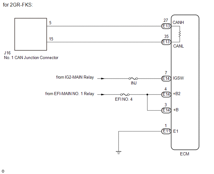
for 2GR-FKS |
A |
|
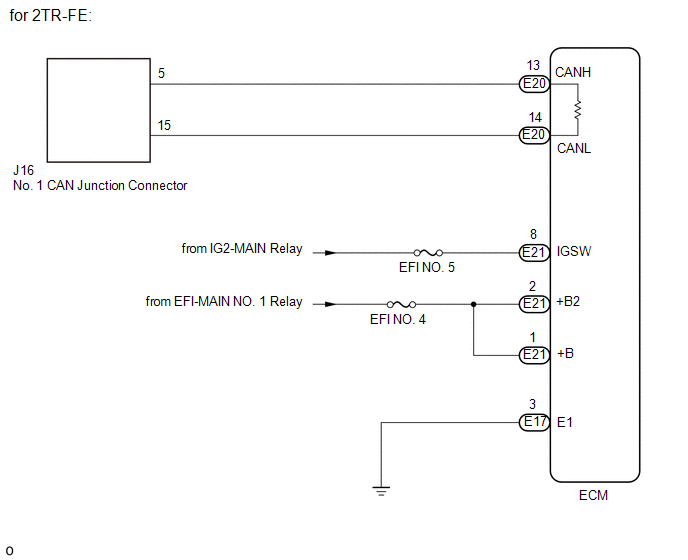
for 2TR-FE |
B |
| B | .gif) |
GO TO STEP 4 |
|
.gif)
|
2. |
CHECK FOR OPEN IN CAN BUS LINES (ECM MAIN LINE) |
(a) Disconnect the cable from the negative (-) battery terminal.
|
(b) Disconnect the ECM connector. |
|
(c) Measure the resistance according to the value(s) in the table below.
Standard Resistance:
|
Tester Connection |
Condition |
Specified Condition |
|---|---|---|
|
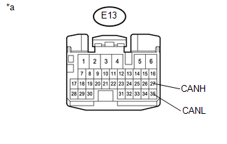
E13-27 (CANH) - E13-35 (CANL) |
Cable disconnected from negative (-) battery terminal |
108 to 132 Ω |
|
*a |
Front view of wire harness connector (to ECM) |
| NG | |
REPAIR OR REPLACE CAN MAIN BUS LINE OR CONNECTOR (ECM MAIN LINE) |
|
|
3. |
CHECK ECM POWER SOURCE CIRCUIT |
(a) Check the ECM power source circuit.
Click here
| OK | |
REPLACE ECM |
| NG | |
REPAIR OR REPLACE HARNESS OR CONNECTOR (POWER SOURCE CIRCUIT) |
|
4. |
CHECK FOR OPEN IN CAN BUS LINES (ECM MAIN LINE) |
(a) Disconnect the cable from the negative (-) battery terminal.
|
(b) Disconnect the ECM connector. |
|
(c) Measure the resistance according to the value(s) in the table below.
Standard Resistance:
|
Tester Connection |
Condition |
Specified Condition |
|---|---|---|
|
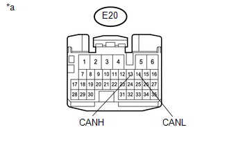
E20-13 (CANH) - E20-14 (CANL) |
Cable disconnected from negative (-) battery terminal |
108 to 132 Ω |
|
*a |
Front view of wire harness connector (to ECM) |
| NG | |
REPAIR OR REPLACE CAN MAIN BUS LINE OR CONNECTOR (ECM MAIN LINE) |
|
|
5. |
CHECK ECM POWER SOURCE CIRCUIT |
(a) Check the ECM power source circuit.
Click here
| OK | |
REPLACE ECM |
| NG | |
REPAIR OR REPLACE HARNESS OR CONNECTOR (POWER SOURCE CIRCUIT) |
 Air Conditioning Amplifier Communication Stop Mode
DESCRIPTION
Detection Item
Symptom
Trouble Area
Air Conditioning Amplifier Communication Stop Mode
Either condition is met:
...
 Main Body ECU Communication Stop Mode
DESCRIPTION
Detection Item
Symptom
Trouble Area
Main Body ECU Communication Stop Mode
Either condition is met:
Communication ...
Other materials:
Reassembly
REASSEMBLY
PROCEDURE
1. INSPECT CENTER NO. 2 SUPPORT BEARING ASSEMBLY
(a) When turning the center No. 2 support bearing assembly with your hand, check
that it turns smoothly without catching and that there are no cracks or damage.
If there are any defects, replace it.
2. INSTALL CENTER NO. ...
Precaution
PRECAUTION
1. EXPRESSIONS OF IGNITION SWITCH
(a) The type of ignition switch used on this model differs according to the specifications
of the vehicle. The expressions listed in the table below are used in this section.
Expression
Ignition Switch (Position)
Engi ...
Image from Camera for Rear View Monitor is Abnormal
DESCRIPTION
The display signal of the rear television camera assembly is transmitted to the
radio and display receiver assembly*1 or navigation receiver assembly*2.
*1: w/o Navigation System
*2: w/ Navigation System
WIRING DIAGRAM
PROCEDURE
1.
CONFIRM ...
