Toyota Tacoma (2015-2018) Service Manual: Removal
REMOVAL
PROCEDURE
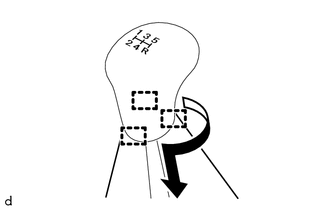
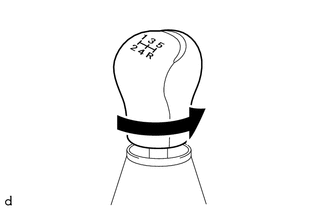
1. REMOVE SHIFT LEVER KNOB SUB-ASSEMBLY (for Automatic Transmission)
|
(a) Using a molding remover A, disengage the 2 claws to separate the shifting hole cover sub-assembly. |
|
|
(b) Rotate the shift lever knob sub-assembly as shown in the illustration to remove it. |
|
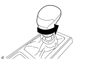
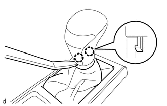
2. REMOVE SHIFT LEVER KNOB SUB-ASSEMBLY (for Manual Transmission)
|
(a) Engage the 3 guides to separate the shifting hole cover sub-assembly as shown in the illustration. |
|
|
(b) Rotate the shift lever knob sub-assembly as shown in the illustration to remove it. |
|
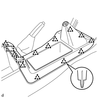
3. REMOVE CONSOLE UPPER PANEL SUB-ASSEMBLY (for Automatic Transmission)
|
(a) Disengage the 12 clips and 2 guides to remove the console upper panel sub-assembly. |
|
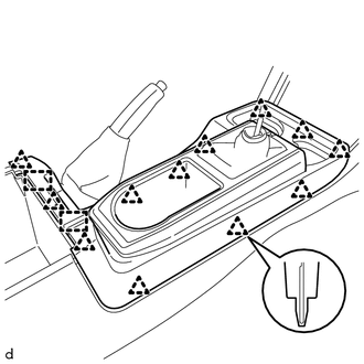
4. REMOVE CONSOLE UPPER PANEL SUB-ASSEMBLY (for Manual Transmission)
|
(a) Disengage the 12 clips and 2 guides to remove the console upper panel sub-assembly. |
|
5. REMOVE CONSOLE BOX CARPET
|
(a) Remove the console box carpet. |
|
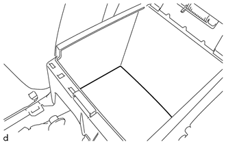
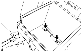
6. REMOVE REAR CONSOLE BOX ASSEMBLY
|
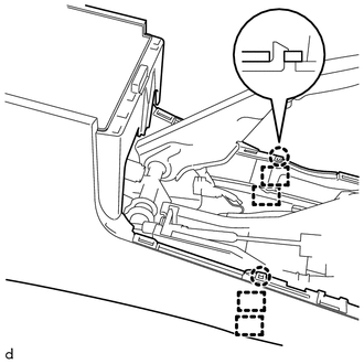
(a) Remove the 2 bolts. |
|
|
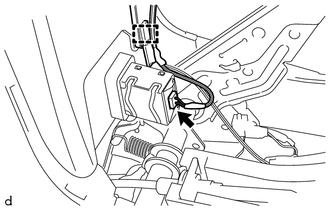
(b) Disconnect the connector and disengage the clamp. |
|
|
(c) Disengage the 2 claws and 4 guides to remove the rear console box assembly. |
|
7. REMOVE FRONT CONSOLE BOX (for Automatic Transmission)
(a) w/ Wireless Charger:
(1) Disconnect the connector.
|
(b) Remove the 3 screws. |
|
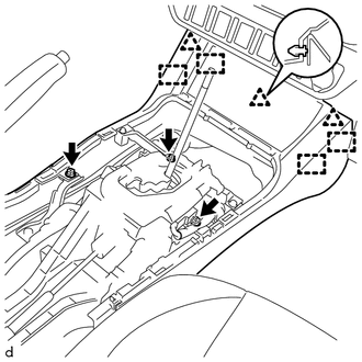
(c) Disengage the 3 clips and 4 guides to remove the front console box.
8. REMOVE FRONT CONSOLE BOX (for Manual Transmission)
(a) w/ Wireless Charger:
(1) Disconnect the connector.
|
(b) Remove the 2 screws. |
|
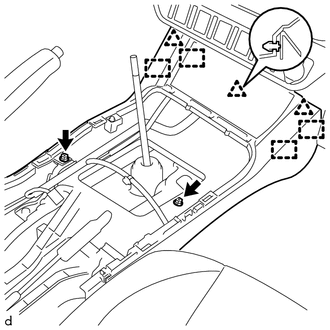
(c) Disengage the 3 clips and 4 guides to remove the front console box.
 Disassembly
DISASSEMBLY
PROCEDURE
1. REMOVE CONSOLE COMPARTMENT DOOR CUSHION
HINT:
Use the same procedure as for the opposite side.
(a) Disengage the claw to remove the console compartment door cu ...
 Installation
INSTALLATION
PROCEDURE
1. INSTALL FRONT CONSOLE BOX (for Automatic Transmission)
(a) When installing a new front console box:
Text in Illustration
*a
...
Other materials:
How To Proceed With Troubleshooting
CAUTION / NOTICE / HINT
HINT:
Use the following procedure to troubleshoot the blind spot monitor system.
*: Use the Techstream.
PROCEDURE
1.
VEHICLE BROUGHT TO WORKSHOP
NEXT
...
Steering Angle Sensor Initialization Incomplete (C1439,C1445)
DESCRIPTION
The skid control ECU (master cylinder solenoid) acquires steering angle sensor
(spiral cable with sensor sub-assembly) zero point every time the ignition switch
is turned to ON and the vehicle is driven at 35 km/h (22 mph) or more for approximately
5 seconds. The ECU also stores t ...
Event data recorder
This vehicle is equipped with an event data recorder (EDR). The main purpose
of an EDR is to record, in certain crash or near crash-like situations, such as
an air bag deployment or hitting a road obstacle, data that will assist in understanding
how a vehicle’s systems performed. The EDR is ...
