Toyota Tacoma (2015-2018) Service Manual: Air Conditioning Compressor Magnetic Clutch Circuit
DESCRIPTION
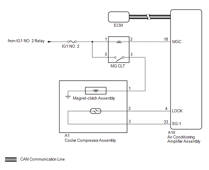
When the air conditioning amplifier assembly is turned on, a magnetic clutch on signal is sent from the MGC terminal of the air conditioning amplifier assembly. Then, the MG CLT relay turns on to operate the magnetic clutch assembly.
WIRING DIAGRAM
CAUTION / NOTICE / HINT
NOTICE:
- ECM malfunctions can affect the storage of this DTC. Therefore, check
all SFI system DTCs and confirm that the system is normal before performing
the following inspection.
- for 2TR-FE (See page
.gif) )
) - for 2GR-FKS (See page )
- for 2TR-FE (See page
- Inspect the fuses for circuits related to this system before performing the following procedure.
PROCEDURE
|
1. |
CHECK FOR DTC (CAN COMMUNICATION SYSTEM) |
(a) Use the Techstream to check if the CAN communication system is functioning normally.
Result|
Result |
Proceed to |
|---|---|
|
CAN DTC is not output |
A |
|
CAN DTC is output |
B |
| B | .gif) |
GO TO CAN COMMUNICATION SYSTEM |
|
.gif)
|
2. |
INSPECT MG CLT RELAY |
(a) Remove the MG CLT relay.
(b) Inspect the MG CLT relay (See page ).
| NG | |
REPLACE MG CLT RELAY |
|
|
3. |
CHECK HARNESS AND CONNECTOR (MG CLT RELAY - POWER SOURCE CIRCUIT) |
(a) Remove the MG CLT relay.
(b) Measure the voltage according to the value(s) in the table below.
Standard Voltage:
|
Tester Connection |
Switch Condition |
Specified Condition |
|---|---|---|
|
MG CLT-1 - Body ground |
Ignition switch ON |
11 to 14 V |
|
MG CLT-5 - Body ground |
Ignition switch ON |
11 to 14 V |
| NG | |
REPAIR OR REPLACE HARNESS OR CONNECTOR |
|
|
4. |
CHECK HARNESS AND CONNECTOR (MG CLT RELAY - AIR CONDITIONING AMPLIFIER ASSEMBLY AND MAGNET-CLUTCH ASSEMBLY) |
(a) Remove the MG CLT relay.
(b) Disconnect the A14 air conditioning amplifier assembly connector.
(c) Disconnect the A1 magnet-clutch assembly connector.
(d) Measure the resistance according to the value(s) in the table below.
Standard Resistance:
|
Tester Connection |
Condition |
Specified Condition |
|---|---|---|
|
MG CLT-2 - A14-18 (MGC) |
Always |
Below 1 Ω |
|
MG CLT-3 - A1-1 (MG+) |
Always |
Below 1 Ω |
|
MG CLT-2 or A14-18 (MGC) - Body ground |
Always |
10 kΩ or higher |
|
MG CLT-3 or A1-1 (MG+) - Body ground |
Always |
10 kΩ or higher |
| NG | |
REPAIR OR REPLACE HARNESS OR CONNECTOR |
|
|
5. |
INSPECT MAGNET-CLUTCH ASSEMBLY |
(a) Remove the magnet-clutch assembly (See page
).
(b) Inspect the magnet-clutch assembly (See page
).
| NG | |
REPLACE MAGNET-CLUTCH ASSEMBLY |
|
|
6. |
INSPECT AIR CONDITIONING AMPLIFIER ASSEMBLY |
(a) Reconnect the A14 air conditioning amplifier assembly connector.
(b) Reconnect the A1 magnet-clutch assembly connector.
(c) Reinstall the MG CLT relay.
|
(d) Measure the voltage according to the value(s) in the table below. Standard Voltage:
|
|
| OK | |
PROCEED TO NEXT SUSPECTED AREA SHOWN IN PROBLEM SYMPTOMS TABLE |
| NG | |
REPLACE AIR CONDITIONING AMPLIFIER ASSEMBLY |
 Lost Communication with ECM (U0100,U0142,U0155)
DESCRIPTION
DTC No.
DTC Detecting Condition
Trouble Area
U0100
No communication with ECM
CAN communication system
...
 Evaporator Temperature Sensor Circuit (B1413)
DESCRIPTION
The cooler thermistor sensor (evaporator temperature sensor) is installed on
the evaporator in the air conditioner unit to detect the temperature of the cooled
air that has passed thr ...
Other materials:
Indicator Circuit
DESCRIPTION
The forward recognition camera sends indicator illumination request signals to
the combination meter assembly via CAN communication.
CAUTION / NOTICE / HINT
NOTICE:
When replacing the combination meter assembly, always replace it with a new one.
If a combination meter assembly wh ...
Operation Check
OPERATION CHECK
INPUT SIGNAL CHECK
*a
+RES
*b
-SET
*c
ON-OFF
*d
CANCEL
(a) Connect the Techstream to the DLC3.
(b) Check the cruise control main switch using the Data List functio ...
Head restraints
Head restraints are provided for all seats.
■ Adjusting the head restraints
Bench type front seat
Up
Pull the head restraints up.
Down
Push the head restraint down while pushing the lock release button.
Separated type front seat
Up
Pull the head restraints up.
Down
Push th ...
