Toyota Tacoma (2015-2018) Service Manual: Installation
INSTALLATION
PROCEDURE
1. INSTALL FRONT CONSOLE BOX (for Automatic Transmission)
|
(a) When installing a new front console box: Text in Illustration
(1) Using a nipper, cut off both ends of the runner portion as shown in the illustration. |
|
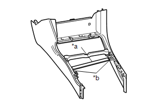
(b) Engage the 4 guides and 3 clips to install the front console box.
(c) Install the 3 screws.
(d) w/ Wireless Charger:
(1) Connect the connector.
2. INSTALL FRONT CONSOLE BOX (for Manual Transmission)
|
(a) When installing a new front console box: Text in Illustration
(1) Using a nipper, cut off both ends of the runner portion as shown in the illustration. |
|
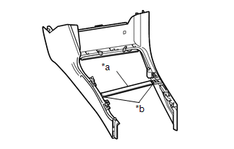
(b) Engage the 4 guides and 3 clips to install the front console box.
(c) Install the 2 screws.
(d) w/ Wireless Charger:
(1) Connect the connector.
3. INSTALL REAR CONSOLE BOX ASSEMBLY
(a) Engage the 4 guides and 2 claws to install the rear console box assembly.
(b) Engage the clamp and connect the connector.
(c) Install the 2 bolts.
4. INSTALL CONSOLE BOX CARPET
(a) Install the console box carpet.
5. INSTALL CONSOLE UPPER PANEL SUB-ASSEMBLY (for Automatic Transmission)
(a) Engage the 2 guides and 12 clips to install the console upper panel sub-assembly.
6. INSTALL CONSOLE UPPER PANEL SUB-ASSEMBLY (for Manual Transmission)
(a) Engage the 2 guides and 12 clips to install the console upper panel sub-assembly.
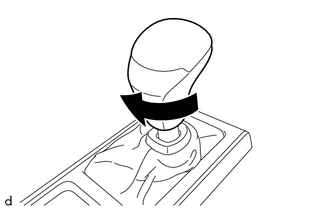
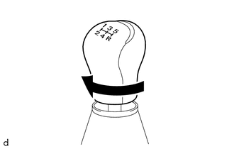
7. INSTALL SHIFT LEVER KNOB SUB-ASSEMBLY (for Automatic Transmission)
|
(a) Rotate the shift lever knob sub-assembly as shown in the illustration to install it. |
|
|
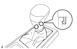
(b) Engage the 2 claws to install the shifting hole cover sub-assembly. |
|
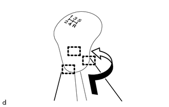
8. INSTALL SHIFT LEVER KNOB SUB-ASSEMBLY (for Manual Transmission)
|
(a) Rotate the shift lever knob sub-assembly as shown in the illustration to install it. |
|
|
(b) Engage the 3 guides to install the shifting hole cover sub-assembly as shown in the illustration. |
|
 Removal
REMOVAL
PROCEDURE
1. REMOVE SHIFT LEVER KNOB SUB-ASSEMBLY (for Automatic Transmission)
(a) Using a molding remover A, disengage the 2 claws to separate the
shifting hole cover sub-as ...
 Reassembly
REASSEMBLY
PROCEDURE
1. INSTALL CONSOLE COMPARTMENT DOOR HINGE SUB-ASSEMBLY
(a) Engage the 2 guides to install the console compartment door hinge
sub-assembly.
...
Other materials:
Identification Information
Vehicle Identification And Serial Numbers
VEHICLE IDENTIFICATION AND SERIAL NUMBERS
1. VEHICLE IDENTIFICATION NUMBER
(a) The vehicle identification number is stamped on the vehicle body and on the
certification label, as shown in the illustration.
A:
Vehicle Identification Number
B:
C ...
Using the interior lights
Interior lights list
Interior light
Personal lights (Access Cab and
Double Cab models)
■Illuminated entry system
When the interior light switch is in the DOOR position, the interior light automatically
turns on/off according to whether the doors are locked/unlocked and whether the ...
USB Audio System Recognition/Play Error
DESCRIPTION
When a USB device or "iPod" is connected to the USB jack of the No. 1 stereo
jack adapter assembly, it must have playable files. The device must also communicate
with and be recognized by the navigation receiver assembly. This diagnosis procedure
is for when a device is ...
