Toyota Tacoma (2015-2018) Service Manual: Rear Body Side Panel Protector
Components
COMPONENTS
ILLUSTRATION
ILLUSTRATION
Installation
INSTALLATION
CAUTION / NOTICE / HINT
HINT:
- Use the same procedure for the RH side and LH side.
- The following procedure is for the LH side.
PROCEDURE
1. INSTALL REAR BODY SIDE PANEL PROTECTOR
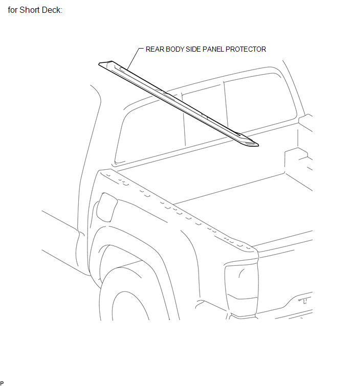
(a) for Short Deck:
(1) Engage the 2 guides and 14 claws to install the rear body side protector.
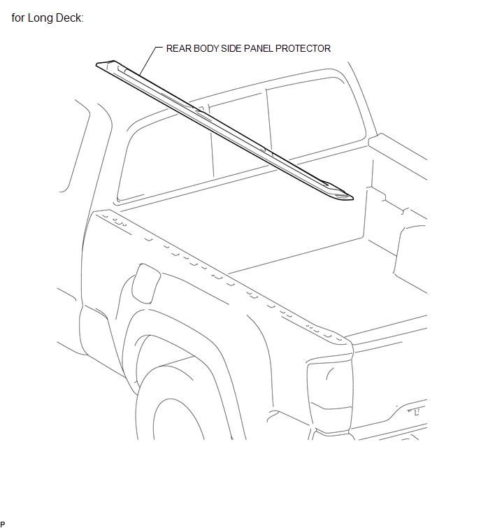
(b) for Long Deck:
(1) Engage the 2 guides and 19 claws to install the rear body side protector.
(c) Remove the protective tape.
2. INSTALL TOP COVER SUB-ASSEMBLY (w/ Tonneau Cover)
(See page .gif) )
)
Removal
REMOVAL
CAUTION / NOTICE / HINT
HINT:
- Use the same procedure for the RH side and LH side.
- The following procedure is for the LH side.
PROCEDURE
1. REMOVE TOP COVER SUB-ASSEMBLY (w/ Tonneau Cover)
(See page .gif) )
)
2. REMOVE REAR BODY SIDE PANEL PROTECTOR
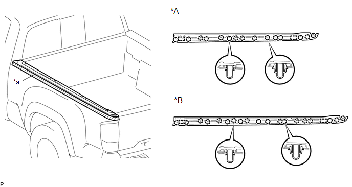
(a) Put protective tape around the rear body side panel protector.
 Text in Illustration
|
*A |
for Short Deck |
*B |
for Long Deck |
|
*a |
Protective Tape |
- |
- |
(b) for Short Deck:
(1) Disengage the 15 claws and 2 guides to remove the rear body side panel protector.
(c) for Long Deck:
(1) Disengage the 19 claws and 2 guides to remove the rear body side panel protector.
 Reassembly
REASSEMBLY
PROCEDURE
1. INSTALL RADIATOR GRILLE MOULDING
(a) Engage the 8 claws to install the radiator grille moulding.
(b) Install the 8 ...

Other materials:
Parts Location
PARTS LOCATION
ILLUSTRATION
ILLUSTRATION
ILLUSTRATION
ILLUSTRATION
...
Reassembly
REASSEMBLY
PROCEDURE
1. TEMPORARILY TIGHTEN FRONT DISC BRAKE BLEEDER PLUG
(a) Provisionally tighten the bleeder plug to the disc brake cylinder.
(b) Install the bleeder plug cap onto the bleeder plug.
2. INSTALL PISTON SEAL
(a) Apply lithium soap base glycol grease to 4 new piston s ...
Removal
REMOVAL
CAUTION / NOTICE / HINT
HINT:
Use the same procedure for both the RH and LH sides.
The procedure described below is for the LH side.
PROCEDURE
1. PRECAUTION
CAUTION:
Be sure to read Precaution thoroughly before servicing (See page
).
NOTICE:
After turning the ign ...
