Toyota Tacoma (2015-2018) Service Manual: Front Differential Oil Temperature Sensor Circuit Low (P17C7)
DESCRIPTION
This DTC is output when a short to ground in the oil temperature sensor is detected.
|
DTC No. |
Detection Item |
DTC Detection Condition |
Trouble Area |
|---|---|---|---|
|
P17C7 |
Front Differential Oil Temperature Sensor Circuit Low |
|
|
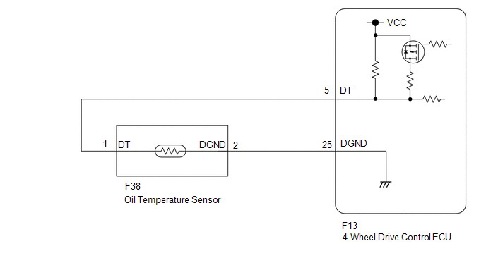
WIRING DIAGRAM
PROCEDURE
|
1. |
CHECK HARNESS AND CONNECTOR (4 WHEEL DRIVE CONTROL ECU AND OIL TEMPERATURE SENSOR - BODY GROUND) |
(a) Disconnect the F13 4 wheel drive control ECU connector.
(b) Disconnect the F38 oil temperature sensor connector.
(c) Measure the resistance according to the value(s) in the table below.
Standard Resistance:
|
Tester Connection |
Condition |
Specified Condition |
|---|---|---|
|
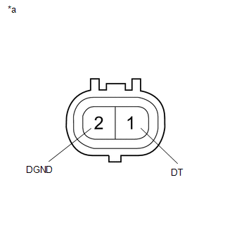
F13-5 (DT) or F38-1 (DT) - Body ground |
Always |
10 kΩ or higher |
|
F13-25 (DGND) or F38-2 (DGND) - Body ground |
Always |
10 kΩ or higher |
| NG | .gif) |
REPAIR OR REPLACE HARNESS OR CONNECTOR |
|
.gif)
|
2. |
INSPECT OIL TEMPERATURE SENSOR |
(a) Disconnect the F38 oil temperature sensor connector.
|
(b) Measure the resistance according to the value(s) in the table below. Standard Resistance:
|
|
| OK | |
REPLACE 4 WHEEL DRIVE CONTROL ECU |
| NG | |
REPLACE OIL TEMPERATURE SENSOR |
 Diagnostic Trouble Code Chart
DIAGNOSTIC TROUBLE CODE CHART
TOUCH SELECT 2-4 AND HIGH-LOW SYSTEM
DTC Code
Detection Item
See page
P163B
4WD ECU Malfunction
...
 Front Differential Oil Temperature Sensor Circuit High (P17C8)
DESCRIPTION
This DTC is output when a short to B+ or open circuit in the oil temperature
sensor is detected.
DTC No.
Detection Item
DTC Detection Condition
...
Other materials:
Inspection
INSPECTION
PROCEDURE
1. INSPECT GENERATOR BRUSH HOLDER ASSEMBLY
(a) Using a vernier caliper, measure the brush length.
Text in Illustration
*a
Length
Standard exposed length:
9.5 to 11.5 mm (0.374 to 0.453 in.)
Minimum ex ...
Installation
INSTALLATION
PROCEDURE
1. INSTALL TRANSMISSION CASE GASKET
(a) Install 2 new transmission case gaskets to the automatic transmission case
sub-assembly.
2. INSTALL MANUAL VALVE
(a) Coat the manual valve with ATF and install it to the transmission valve body
assembly.
3. INSTALL TRANSMISSION ...
Removal
REMOVAL
CAUTION / NOTICE / HINT
NOTICE:
If one of the camshaft timing gear bolts is already removed, do not remove any
other camshaft timing gear bolts.
PROCEDURE
1. REMOVE NO. 2 ENGINE UNDER COVER SUB-ASSEMBLY (w/ Off Road Package)
2. REMOVE NO. 1 ENGINE UNDER COVER SUB-ASSEMBLY
3. REMOVE ...
