Toyota Tacoma (2015-2018) Service Manual: Disassembly
DISASSEMBLY
PROCEDURE
1. REMOVE CONSOLE COMPARTMENT DOOR CUSHION
HINT:
Use the same procedure as for the opposite side.
|
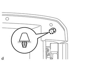
(a) Disengage the claw to remove the console compartment door cushion. |
|
2. REMOVE CONSOLE COMPARTMENT DOOR SUB-ASSEMBLY
|
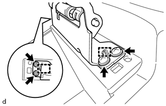
(a) Remove the 2 screws. |
|
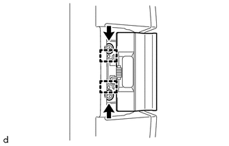
(b) Disengage the 2 guides to remove the console compartment door lock lever.
|
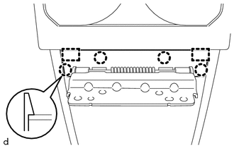
(c) Remove the 6 screws. Text in Illustration
|
|
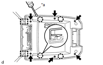
(d) Using a screwdriver with its tip wrapped in protective tape, disengage the 4 claws and 2 guides to remove the console compartment door sub-assembly.
3. REMOVE CONSOLE COMPARTMENT OUTER DOOR
|
(a) Remove the 4 screws. |
|
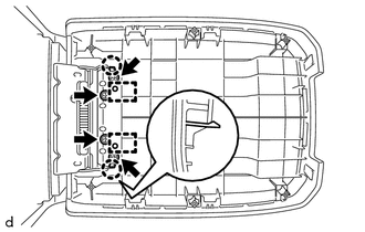
(b) Disengage the 2 claws and 2 guides to remove the console compartment outer door.
4. REMOVE CONSOLE COMPARTMENT DOOR HINGE SUB-ASSEMBLY
|
(a) Disengage the 4 claws and 2 guides to remove the console compartment door moulding cover. |
|
|
(b) Remove the 4 screws. |
|
(c) Disengage the 2 guides to remove the console compartment door hinge sub-assembly.
 Components
COMPONENTS
ILLUSTRATION
ILLUSTRATION
...
 Removal
REMOVAL
PROCEDURE
1. REMOVE SHIFT LEVER KNOB SUB-ASSEMBLY (for Automatic Transmission)
(a) Using a molding remover A, disengage the 2 claws to separate the
shifting hole cover sub-as ...
Other materials:
Low Pitched Horn
Components
COMPONENTS
ILLUSTRATION
Inspection
INSPECTION
PROCEDURE
1. INSPECT LOW PITCHED HORN ASSEMBLY
(a) Check the operation.
(1) Apply battery voltage to the terminal 1 and body ground, and check
that the low pitched horn assembly sounds.
Text in Illustration
...
Brake Warning Light Remains ON
DESCRIPTION
The BRAKE warning light comes on when brake fluid is insufficient, the parking
brake is applied or the EBD is defective.
WIRING DIAGRAM
CAUTION / NOTICE / HINT
NOTICE:
When replacing the skid control ECU (master cylinder solenoid), perform
calibration (See page
...
Clearance Warning Buzzer
Components
COMPONENTS
ILLUSTRATION
Installation
INSTALLATION
PROCEDURE
1. INSTALL NO. 1 CLEARANCE WARNING BUZZER
(a) Connect the connector.
(b) Engage the clamp to install the No. 1 clearance warning buzzer.
2. INSTALL INSTRUMENT PANEL SUB-ASSEMBLY
(See page )
Removal
REMOVAL
...
