Toyota Tacoma (2015-2018) Service Manual: Precaution
PRECAUTION
CAUTION:
- The vehicle is equipped with SRS, which consists of a driver airbag, front passenger airbag, side airbags and curtain shield airbags and knee airbags. Failure to carry out service operations in the correct sequence could cause the SRS to unexpectedly deploy during servicing, possibly leading to a serious accident. Further more, if a mistake is made in servicing the SRS, it is possible that the SRS may fail to operate when required. Before performing servicing (including removal or installation of parts, inspection or replacement), be sure to read the following items carefully, then follow the correct procedures indicated in the repair manual.
- Wait at least 90 seconds after the ignition switch is turned to the LOCK position and the negative (-) terminal cable is disconnected from the battery. (The SRS is equipped with a back-up power source, so if work is started within 90 seconds after disconnecting the negative (-) terminal cable of the battery, the SRS may be deployed.)
- Do not directly expose the horn button assembly, front panel passenger airbag assembly, lower No. 1 instrument panel airbag assembly, lower No. 2 instrument panel airbag assembly, airbag sensor assembly, front airbag sensor, front seat airbag assembly, side airbag sensor assembly, curtain shield airbag assembly, rear airbag sensor, seat position airbag sensor or occupant detection ECU to hot air or flames.
- Be sure to perform the initialization of the occupant detection ECU
if any of the following conditions occur (See page
.gif) ). If the initialization is not performed,
the SRS may not operate properly.
). If the initialization is not performed,
the SRS may not operate properly.
- The occupant detection ECU is replaced.
- Accessories (seatback tray, seat cover, etc.) are installed onto the vehicle.
- The passenger seat is removed from the vehicle, and then reinstalled or replaced.
- The passenger airbag ON/OFF indicator light (OFF) comes on when the passenger seat is not occupied.
- The vehicle is brought to the workshop for repair due to an accident or collision.
NOTICE:
- Malfunction symptoms of the SRS are difficult to confirm, so DTCs are the most important source of information when troubleshooting. When troubleshooting the SRS, always inspect DTCs before disconnecting the battery.
- Even in the case of a minor collision when the SRS does not deploy, the horn button assembly, instrument panel passenger without door airbag assembly, lower No. 1 instrument panel airbag assembly, lower No. 2 instrument panel airbag assembly, airbag sensor assembly, front airbag sensor, front seat airbag assembly, side airbag sensor assembly, Curtain shield airbag assembly, rear airbag sensor, seat position airbag sensor and occupant detection ECU should be inspected.
- Before repair work, remove the airbag sensor if any kind of shock is likely to occur to the airbag sensor during the operation.
- Never use SRS parts from another vehicle. When replacing parts, replace them with new ones.
- Never disassemble or repair the horn button assembly, instrument panel passenger without door airbag assembly, lower No. 1 instrument panel airbag assembly, lower No. 2 instrument panel airbag assembly, airbag sensor assembly, front airbag sensor, front seat airbag assembly, side airbag sensor assembly, Curtain shield airbag assembly, rear airbag sensor, seat position airbag sensor or occupant detection ECU in order to reuse it.
- If the horn button assembly, instrument panel passenger without door airbag assembly, lower No. 1 instrument panel airbag assembly, lower No. 2 instrument panel airbag assembly, airbag sensor assembly, front airbag sensor, front seat airbag assembly, side airbag sensor assembly, curtain shield airbag assembly, rear airbag sensor, seat position airbag sensor or occupant detection ECU has been dropped, or if there are any cracks, dents or other defects in the case, bracket or connector, replace it with a new one.
- Use a volt/ohmmeter with high impedance (10 kΩ/V minimum) for troubleshooting the electrical circuits.
- Information labels are attached to the periphery of the SRS components. Follow the instructions in the cautions.
- After work on the SRS is completed, perform the SRS warning light check
(See page ).
- When the negative (-) terminal cable is disconnected from the battery, the memory will be cleared. Thus, be sure to make a record of the contents stored in each system before starting work. When the work is finished, reset each system, as it was before. Never use a back-up power supply from outside the vehicle to avoid erasing the memory in any system.
- If the vehicle is equipped with a mobile communication system, refer to the precaution in the INTRODUCTION section.
1. HANDLING PRECAUTIONS FOR AIRBAG SENSORS
HINT:
In order to prevent unexpected airbag deployment, disconnect the following connectors before inspecting parts such as wire harnesses, if the application of tester probes to the airbag sensor assembly connector is necessary.
- Airbag Sensor assembly
- Front Airbag Sensor LH
- Front Airbag Sensor RH
- Side Airbag Sensor Assembly LH
- Side Airbag Sensor Assembly RH
- Rear Airbag Sensor LH
- Rear Airbag Sensor RH
(a) Before starting the following operations, wait for at least 90 seconds after disconnecting the negative (-) terminal cable from the battery:
(1) Replacement of the airbag sensors.
(2) Adjustment of the front/rear doors of the vehicle equipped with the side airbag and curtain shield airbag (fitting adjustment).
(b) When connecting or disconnecting the airbag sensor connectors, ensure that each sensor is installed in the vehicle.
(c) Do not use the airbag sensors which has been dropped during the operation or transportation.
(d) Do not disassemble the airbag sensors.
(e) If engine is run immediately after reconnecting negative battery terminal cable, keep it at less than 2000 rpm for at least 1 minute.
(f) If the engine exceeds 2000 rpm, the clutch is automatically disengaged by the compressor protection control system.
2. INSPECTION PROCEDURE FOR VEHICLE INVOLVED IN ACCIDENT
(a) When the airbag has not deployed, check for DTCs by checking the SRS warning light blinking patterns or using a Techstream. If any DTCs are present, perform troubleshooting for those DTCs.
(b) When any of the airbags have deployed due to the collision, be sure to replace all sensors in the damaged areas and airbag sensor assembly.
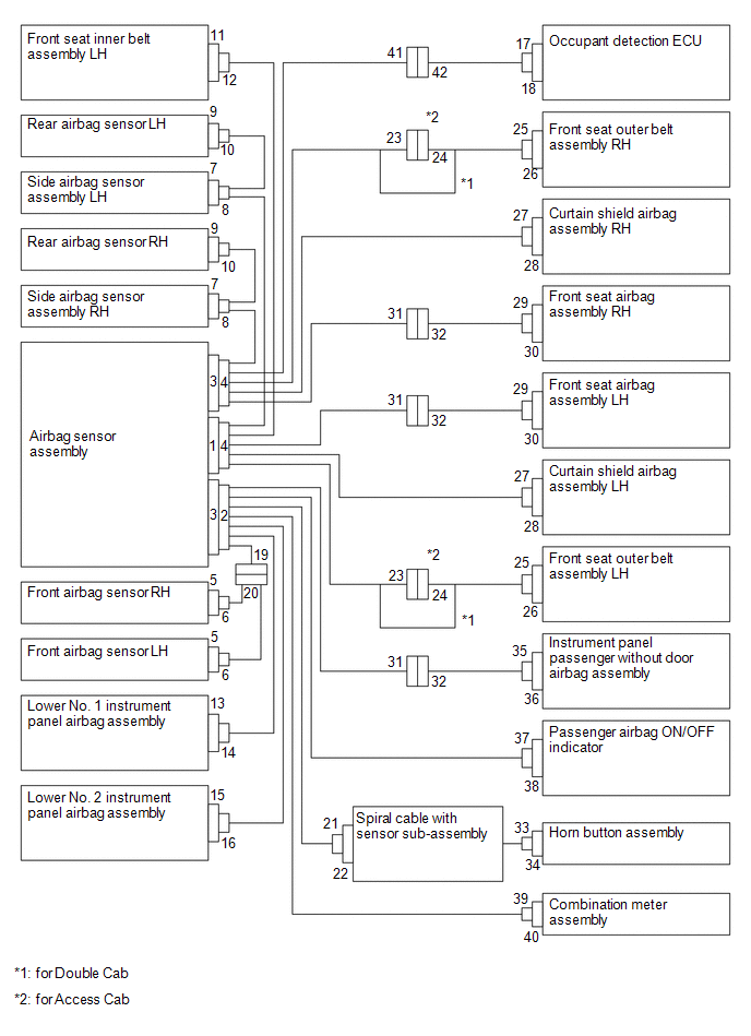
3. SRS CONNECTORS
HINT:
SRS connectors are located as shown in the following illustration.
|
No. |
Connector Type |
Application |
|---|---|---|
|
(1) |
Terminal Twin-Lock Mechanism |
Connectors 2, 4, 6, 8, 10, 19, 20, 21, 29, 31 |
|
(2) |
Activation Prevention Mechanism |
Connectors 2, 4, 22, 30, 32 |
|
(3) |
Half Connection Prevention Mechanism |
Connectors 6, 8, 10, 20, 21, 23, 29 |
|
(4) |
Connector Lock Mechanism (1) |
Connectors 19, 25, 27, 33, 35 |
|
(5) |
Connector Lock Mechanism (2) |
Connectors 2, 4 |
|
(6) |
Improper Connection Prevention Lock Mechanism |
Connectors 1, 3 |
(a) All connectors in the SRS except the seat position airbag sensor connector and the occupant detection ECU connector are colored yellow to distinguish them from other connectors. Some connectors have special functions, and are specially designed for the SRS. These connectors use durable gold-plated terminals, and are placed in the locations shown above to ensure high reliability.
(1) Terminal twin-lock mechanism:
Each connector has a two-piece component consisting of a housing and a spacer. This design enables the terminal to be locked securely by two locking devices (the retainer and the lance) to prevent the terminals from becoming disconnected.
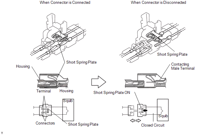
(2) Activation prevention mechanism:
Each connector contains a short spring plate. When the connector is disconnected, the short spring plate automatically connects the positive (+) and negative (-) terminals of the squib.
(3) Half connection prevention mechanism:
If the connector is not completely connected, the connector is disconnected due to the spring operation so that no continuity exists.
(4) Connector lock mechanism (1):
Locking the connector lock button connects the connector securely.

(5) Connector lock mechanism (2):
Both the primary lock with holder lances and the secondary lock with retainer prevent the connectors from becoming disconnected.
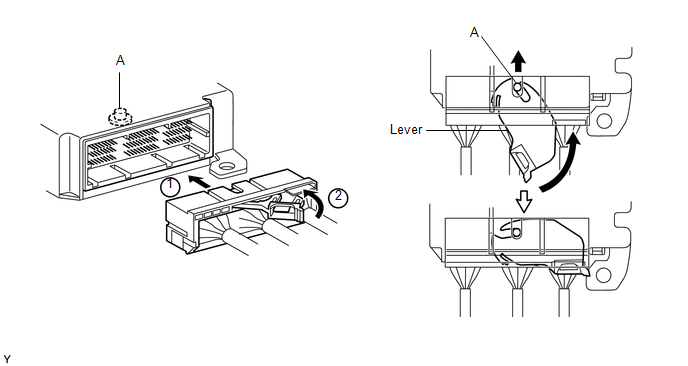
(6) Improper connection prevention lock mechanism:
When connecting the holder, the lever is pushed into the end by rotating around the A axis to lock the holder securely.
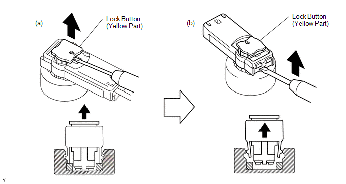
4. DISCONNECTION OF CONNECTORS FOR HORN BUTTON ASSEMBLY, LOWER INSTRUMENT PANEL AIRBAG ASSEMBLY, INSTRUMENT PANEL PASSENGER WITHOUT DOOR AIRBAG ASSEMBLY AND CURTAIN SHIELD AIRBAG ASSEMBLY
(a) Release the lock button (yellow part) of the connector using a screwdriver.
(b) Insert the screwdriver tip between the connector and the base, and then raise the connector.
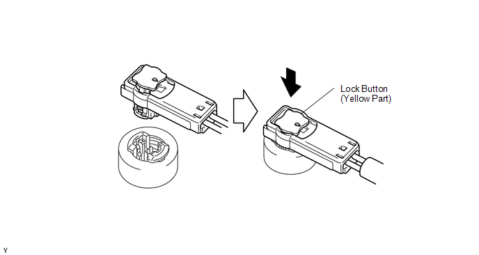
5. CONNECTION OF CONNECTORS FOR HORN BUTTON ASSEMBLY, LOWER INSTRUMENT PANEL AIRBAG ASSEMBLY, INSTRUMENT PANEL PASSENGER WITHOUT DOOR AIRBAG ASSEMBLY AND CURTAIN SHIELD AIRBAG ASSEMBLY
(a) Connect the connector.
(b) Push down securely on the lock button (yellow part) of the connector. (When locking, a click sound can be heard.)
6. DISCONNECTION OF CONNECTOR FOR FRONT SEAT AIRBAG ASSEMBLY
(a) Place a finger on the slider, slide the slider to release the lock, and then disconnect the connector.
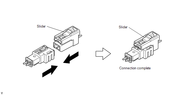
7. CONNECTION OF CONNECTOR FOR FRONT SEAT AIRBAG ASSEMBLY
(a) Connect the connector as shown in the illustration. (When locking, make sure that the slider returns to its original position and a click sound can be heard.)
HINT:
When connecting, the slider will slide. Be sure not to touch the slider while connecting, as this may result in an insecure fit.

8. DISCONNECTION OF CONNECTOR FOR INSTRUMENT PANEL PASSENGER WITHOUT DOOR AIRBAG ASSEMBLY
(a) Place a finger on the slider, slide the slider to release the lock, and then disconnect the connector.
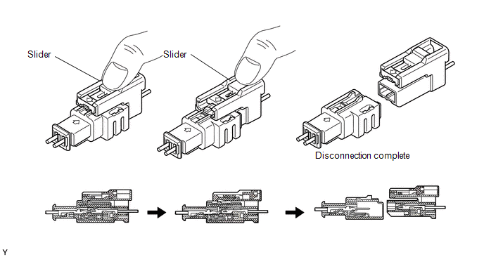
9. CONNECTION OF CONNECTOR FOR INSTRUMENT PANEL PASSENGER WITHOUT DOOR AIRBAG ASSEMBLY
(a) Connect the connector as shown in the illustration. (When locking, make sure that the slider returns to its original position and a click sound can be heard.)
HINT:
When connecting, the slider will slide. Be sure not to touch the slider while connecting, as this may result in an insecure fit.
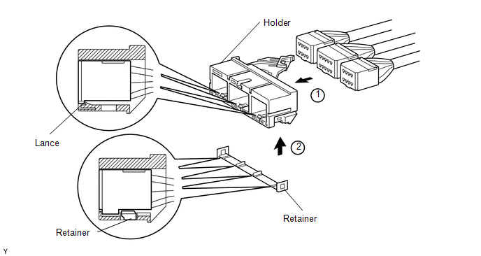
10. DISCONNECTION OF CONNECTOR FOR AIRBAG SENSOR ASSEMBLY
(a) Pull the lever by pushing part A as shown in the illustration and disconnect the holder (with connectors).
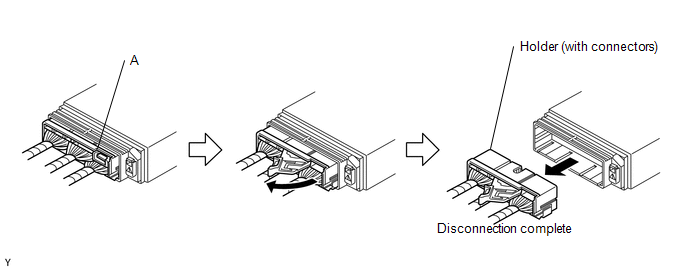
HINT:
Perform the following procedures when replacing the holder.
(b) Remove the holder.
(1) Using a screwdriver, unlock the retainer.
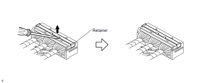
(2) Release the fitting lances and remove the holder.
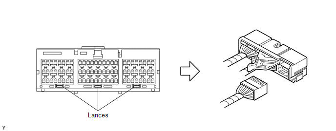
(c) Install the holder.
(1) Install the connectors into the holder. (When locking, a click sound can be heard.)
HINT:
The retainer is locked when the holder is connected.
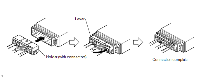
11. CONNECTION OF CONNECTOR FOR AIRBAG SENSOR ASSEMBLY
(a) Firmly insert the holder (with connectors) until it cannot be pushed any further.
(b) Push the lever to connect the holder (with connectors). (When locking, a click sound can be heard.)
HINT:
The holder slides when connecting. Holding the holder when connecting may result in an insecure connection.
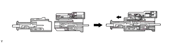
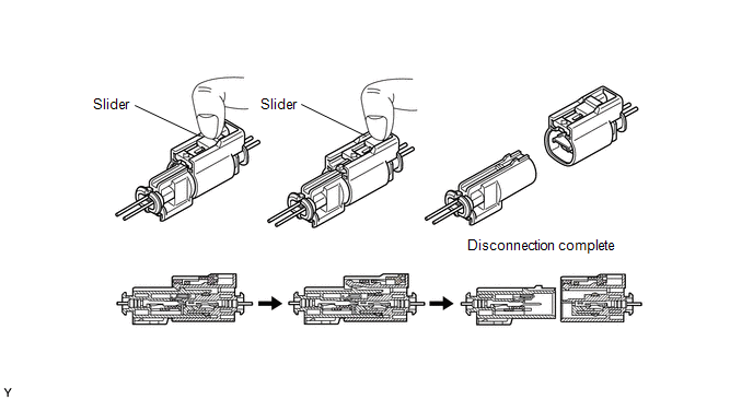
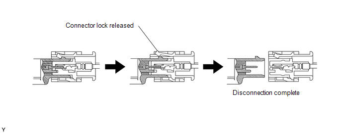
12. DISCONNECTION OF CONNECTORS FOR FRONT AIRBAG SENSOR, SIDE AIRBAG SENSOR ASSEMBLY AND REAR AIRBAG SENSOR
(a) While holding both outer flank sides, slide the outer in the direction shown by the arrow.
(b) When the connector lock is released, the connectors are disconnected.
HINT:
Be sure to hold both outer flank sides. Holding the top and bottom sides will make disconnection difficult.
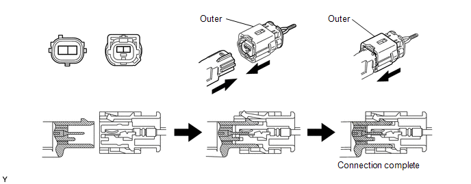
13. CONNECTION OF CONNECTORS FOR FRONT AIRBAG SENSOR, SIDE AIRBAG SENSOR ASSEMBLY AND REAR AIRBAG SENSOR
(a) Connect the connector as shown in the illustration. (When locking, make sure that the outer returns to its original position and a click sound can be heard.)
HINT:
When connecting, the outer will slide. Be sure not to hold the outer while connecting, as it may result in an insecure fit.
 Parts Location
PARTS LOCATION
ILLUSTRATION
ILLUSTRATION
ILLUSTRATION
ILLUSTRATION
ILLUSTRATION
...
 System Diagram
SYSTEM DIAGRAM
Transmitting ECU
(Transmitter)
Receiving ECU
Signal
Communication Method
Airbag Sensor Assembly
ECM
...
Other materials:
Dtc Check / Clear
DTC CHECK / CLEAR
1. CHECK FOR DTC
HINT:
When using the Techstream with the engine switch off, connect the Techstream
to the DLC3 and turn a courtesy light switch on and off at intervals of 1.5 seconds
or less until communication between the Techstream and the vehicle begins. Then
select th ...
On-vehicle Inspection
ON-VEHICLE INSPECTION
PROCEDURE
1. INSPECT DRIVER SEAT BELT WARNING LIGHT
HINT:
The seat belt warning light on the combination meter assembly is used for both
the driver seat and front passenger seat.
(a) Turn the ignition switch to ON.
(b) When the driver seat belt is not fastened, check th ...
Short in GPS Antenna (B15C0,B15C1)
DESCRIPTION
These DTCs are stored when a malfunction occurs in the navigation antenna assembly.
DTC No.
DTC Detection Condition
Trouble Area
B15C0
Navigation antenna error
Navigation antenna assembly
Radio and ...
