Toyota Tacoma (2015-2018) Service Manual: Parts Location
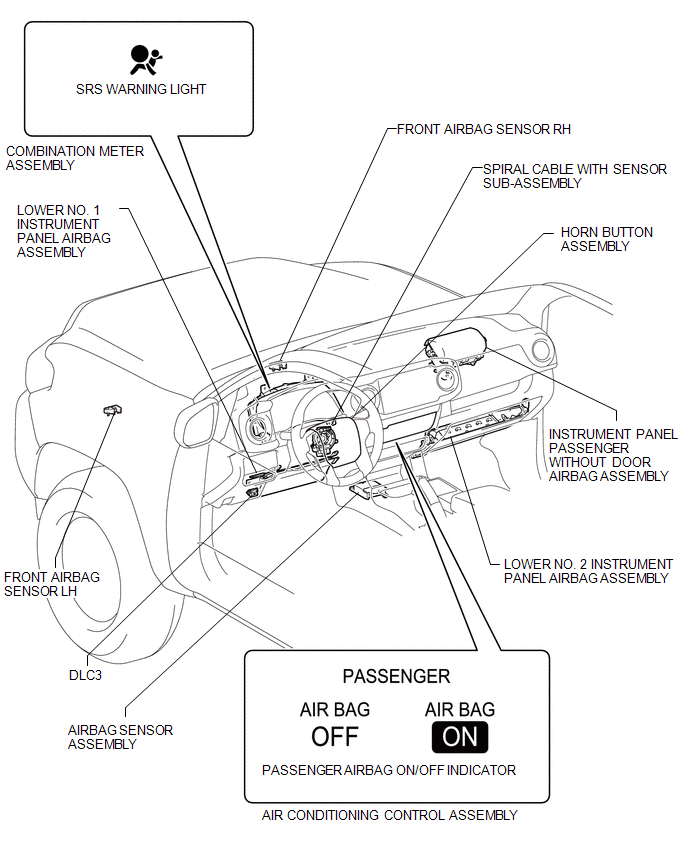
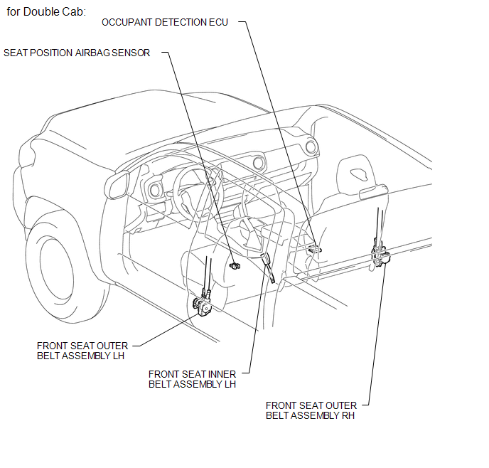
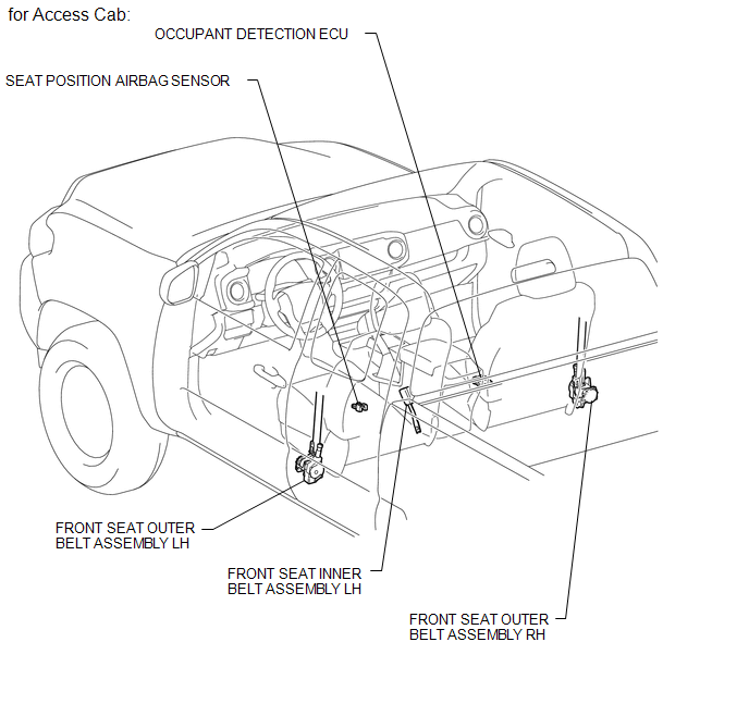
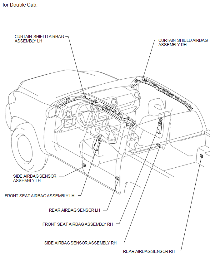
PARTS LOCATION
ILLUSTRATION
ILLUSTRATION
ILLUSTRATION
ILLUSTRATION
ILLUSTRATION
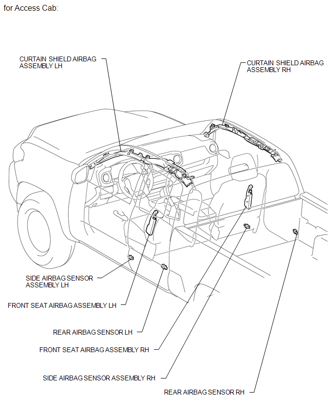
 Airbag System
...
 Precaution
PRECAUTION
CAUTION:
The vehicle is equipped with SRS, which consists of a driver airbag,
front passenger airbag, side airbags and curtain shield airbags and knee
airbags. Failure to ...
Other materials:
Open or Short in Rear Speed Sensor RH Circuit (C1407,C1408)
DESCRIPTION
Refer to DTCs C1401 and C1402 (See page ).
DTC Code
DTC Detection Condition
Trouble Area
C1407
C1408
Either condition is met:
An open in the speed sensor signal circuit continues for 0.5
seconds or mor ...
Installation
INSTALLATION
PROCEDURE
1. INSTALL LOWER NO. 2 INSTRUMENT PANEL AIRBAG ASSEMBLY
(a) Connect the airbag connector.
NOTICE:
When handling the airbag connector, take care not to damage the airbag
wire harness.
(b) Push in the airbag conn ...
Vehicle Speed Sensor "A" No Signal (P050031)
DESCRIPTION
The speed sensor detects the wheel speed and sends the appropriate signals to
the skid control ECU. The skid control ECU converts these wheel speed signals into
a pulse signal and outputs it to the ECM via the combination meter. The ECM determines
the vehicle speed based on the fr ...
