Toyota Tacoma (2015-2018) Service Manual: Removal
REMOVAL
CAUTION / NOTICE / HINT
HINT:
- Use the same procedure for the RH side and LH side.
- The procedure listed below is for the LH side.
PROCEDURE
1. REMOVE FRONT WHEEL
2. REMOVE NO. 1 ENGINE UNDER COVER SUB-ASSEMBLY
3. SEPARATE FRONT STABILIZER LINK ASSEMBLY LH
|
(a) Remove the nut and separate the front stabilizer link assembly LH from the steering knuckle. HINT: If the ball joint turns together with the nut, use a socket hexagon wrench 6 mm to hold the stud. |
|
.png)
4. SEPARATE FRONT STABILIZER LINK ASSEMBLY RH
HINT:
Use the same procedure for the RH side and LH side.
5. REMOVE FRONT NO. 1 STABILIZER BRACKET LH
.gif)
6. REMOVE FRONT NO. 1 STABILIZER BRACKET RH
HINT:
Use the same procedure for the RH side and LH side.
7. REMOVE FRONT STABILIZER BAR
8. SEPARATE TIE ROD END SUB-ASSEMBLY
9. REMOVE FRONT SHOCK ABSORBER WITH COIL SPRING
|
(a) Remove the bolt, nut and the washer on the lower side of the front shock absorber with coil spring. |
|
.png)
|
(b) Remove the 3 nuts on the upper side of the front shock absorber with coil spring. |
|
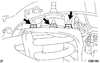
(c) Remove the front shock absorber with coil spring.
10. REMOVE FRONT SUPPORT TO FRONT SHOCK ABSORBER NUT
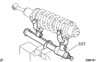
|
(a) Secure SST in a vise. SST: 09727-00060 SST: 09727-30021 09727-00010 09727-00031 |
|
|
(b) Attach the arm of SST to the diameter of the front coil spring. CAUTION:
|
|
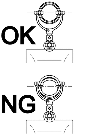
(c) Using SST, compress the front coil spring.
CAUTION:
- If the front coil spring bends during the compression, immediately stop the compression and reinstall SST.
- Do not compress the spring until the coil springs contact each other.
- Do not use an impact wrench. It will damage SST.
|
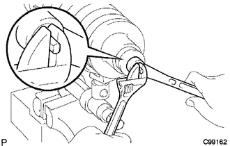
(d) Confirm that the front coil spring becomes free and while holding the shock absorber rod, remove the front support to front shock absorber nut. CAUTION: Do not remove the front support to front shock absorber nut when the front coil spring is not free. |
|
11. REMOVE FRONT SHOCK ABSORBER CUSHION RETAINER
12. REMOVE FRONT SHOCK ABSORBER NO. 1 CUSHION
13. REMOVE FRONT SUSPENSION SUPPORT SUB-ASSEMBLY
14. REMOVE FRONT SHOCK ABSORBER CUSHION RETAINER
15. REMOVE FRONT COIL SPRING
 Inspection
INSPECTION
PROCEDURE
1. INSPECT FRONT SHOCK ABSORBER ASSEMBLY
(a) Compress and extend the shock absorber rod and check that there is no abnormal
resistance or unusual sound during operation.
I ...
 Disposal
DISPOSAL
PROCEDURE
1. DISPOSE OF FRONT SHOCK ABSORBER ASSEMBLY
(a) Fully extend the shock absorber piston rod, and fix it at an angle in a vise
or similar tool.
(b) Using a drill or similar to ...
Other materials:
Problem Symptoms Table
PROBLEM SYMPTOMS TABLE
HINT:
Use the table below to help determine the cause of problem symptoms.
If multiple suspected areas are listed, the potential causes of the symptom
are listed in order of probability in the "Suspected Area" column of the
table. Check each sym ...
Terminals Of Ecu
TERMINALS OF ECU
1. AIRBAG SENSOR ASSEMBLY
Terminal No.
Terminal Symbol
Destination
A21-1
P2+
Instrument panel passenger without door airbag assembly (Front passenger
side squib 2nd step)
A21-2
...
Diagnostic Trouble Code Chart
DIAGNOSTIC TROUBLE CODE CHART
Forward Recognition Camera System
DTC No.
Detection Item
Link
C1A0A
Front Radar Sensor Region Code Mismatch
C1A47
Steering Angle Sensor
...
