Toyota Tacoma (2015-2018) Service Manual: System Diagram
SYSTEM DIAGRAM
|
Transmitting ECU (Transmitter) |
Receiving ECU |
Signal |
Communication Method |
|---|---|---|---|
|
Airbag Sensor Assembly |
ECM |
Crash detection signal |
CAN |
|
Airbag Sensor Assembly |
Combination Meter Assembly |
|
CAN |
|
Combination Meter Assembly |
Airbag Sensor Assembly |
Vehicle speed signal |
CAN |
|
ECM |
Airbag Sensor Assembly |
|
CAN |
 Precaution
PRECAUTION
CAUTION:
The vehicle is equipped with SRS, which consists of a driver airbag,
front passenger airbag, side airbags and curtain shield airbags and knee
airbags. Failure to ...
 How To Proceed With Troubleshooting
CAUTION / NOTICE / HINT
HINT:
*: Use the Techstream.
PROCEDURE
1.
VEHICLE BROUGHT TO WORKSHOP
NEXT
...
Other materials:
On-vehicle Inspection
ON-VEHICLE INSPECTION
PROCEDURE
1. CHECK STEERING WHEEL FREE PLAY
(a) Stop the vehicle and align the tires facing straight ahead.
(b) Gently turn the steering wheel right and left by hand, and check
the steering wheel free play.
Maximum free play:
30 mm (1.18 in.)
Text i ...
Fail-safe Chart
FAIL-SAFE CHART
1. PULSE FAILURE OR DISPLACEMENT OF NON-DETECTION RANGE TO THE OPENING DIRECTION
(a) If the pulse sensor built into the power window regulator motor malfunctions,
the power window control system enters fail-safe mode.
Power Window Regulator Master Switch Assembly, Front Power Wi ...
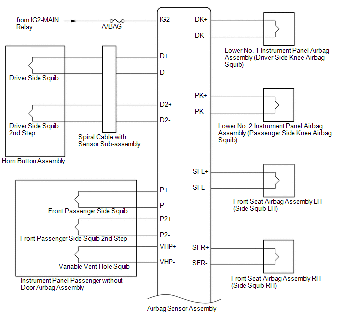
Short in Front Passenger Side Squib Circuit (B1805/52-B1808/52)
DESCRIPTION
The front passenger side squib circuit consists of the airbag sensor assembly
and the instrument panel passenger without door airbag assembly.
The circuit instructs the SRS to deploy when deployment conditions are met.
These DTCs are recorded when a malfunction is detected in the fr ...
