Toyota Tacoma (2015-2018) Service Manual: Front Airbag Sensor LH Circuit Malfunction (B1615/14)
DESCRIPTION
The front airbag sensor LH consists of parts such as the diagnostic circuit and the frontal detection sensor.
When the airbag sensor assembly receives signals from the frontal deceleration sensor, it determines whether or not the SRS should be activated.
DTC B1615/14 is set when a malfunction is detected in the front airbag sensor LH circuit.
|
DTC No. |
DTC Detecting Condition |
Trouble Areas |
|---|---|---|
|
B1615/14 |
|
|
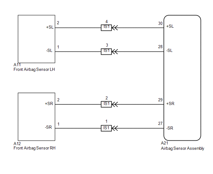
WIRING DIAGRAM
CAUTION / NOTICE / HINT
NOTICE:
After turning the ignition switch off, waiting time may be required before disconnecting
the cable from the negative (-) battery terminal. Therefore, make sure to read the
disconnecting the cable from the negative (-) battery terminal notices before proceeding
with work (See page .gif) ).
).
PROCEDURE
|
1. |
CHECK CONNECTION OF CONNECTORS |
(a) Turn the ignition switch off.
(b) Disconnect the negative (-) terminal cable from the battery, and wait for at least 90 seconds.
(c) Check that the connectors are properly connected to the airbag sensor assembly and the front airbag sensor LH.
OK:
The connectors are properly connected.
| NG | .gif) |
CONNECT CONNECTORS |
|
.gif)
|
2. |
CHECK CONNECTOR |
(a) Check that the connectors (on the airbag sensor assembly side and front airbag
sensor LH side) are not damaged (See page ).
OK:
The connectors are not deformed or damaged.
| NG | |
REPLACE WIRE HARNESS |
|
|
3. |
CHECK FRONT AIRBAG SENSOR LH CIRCUIT (FOR OPEN) |
|
(a) Disconnect the connectors from the airbag sensor assembly and the front airbag sensor LH. |
|
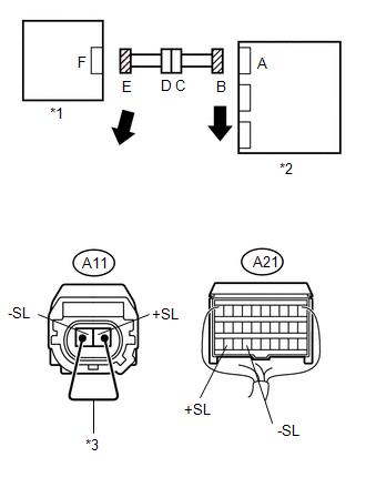
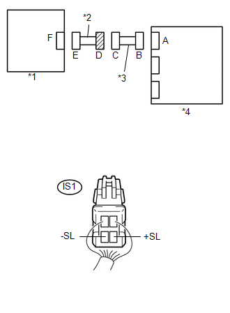
(b) Using a service wire, connect A11-2 (+SL) and A11-1 (-SL) of connector E.
NOTICE:
Do not forcibly insert the service wire into the terminals of the connector when connecting.
(c) Measure the resistance according to the value(s) in the table below.
Standard Resistance:
|
Tester Connection |
Condition |
Specified Condition |
|---|---|---|
|
A21 -30 (+SL) - A21-28 (-SL) |
Always |
Below 1 Ω |
|
*1 |
Front Airbag Sensor LH |
|
*2 |
Airbag Sensor Assembly |
|
*3 |
Service Wire |
| NG | |
GO TO STEP 9 |
|
|
4. |
CHECK FRONT AIRBAG SENSOR LH CIRCUIT (FOR SHORT) |
|
(a) Disconnect the service wire from connector E. |
|
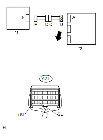
(b) Measure the resistance according to the value(s) in the table below.
Standard Resistance:
|
Tester Connection |
Condition |
Specified Condition |
|---|---|---|
|
A21 -30 (+SL) - A21-28 (-SL) |
Always |
1 MΩ or Higher |
|
*1 |
Front Airbag Sensor LH |
|
*2 |
Airbag Sensor Assembly |
| NG | |
GO TO STEP 10 |
|
|
5. |
CHECK FRONT AIRBAG SENSOR LH CIRCUIT (TO B+) |
|
(a) Connect the negative (-) terminal cable to the battery, and wait for at least 2 seconds. |
|
(b) Turn the ignition switch to ON.
(c) Measure the voltage according to the value(s) in the table below.
Standard Voltage:
|
Tester Connection |
Switch Condition |
Specified Condition |
|---|---|---|
|
A21 -30 (+SL) - Body ground |
Ignition switch ON |
Below 1 V |
|
A21-28 (-SL) - Body ground |
Ignition switch ON |
Below 1 V |
|
*1 |
Front Airbag Sensor LH |
|
*2 |
Airbag Sensor Assembly |
| NG | |
GO TO STEP 11 |
|
|
6. |
CHECK FRONT AIRBAG SENSOR LH CIRCUIT (TO GROUND) |
|
(a) Turn the ignition switch off. |
|
(b) Disconnect the negative (-) terminal cable from the battery, and wait for at least 90 seconds.
(c) Measure the resistance according to the value(s) in the table below.
Standard Resistance:
|
Tester Connection |
Condition |
Specified Condition |
|---|---|---|
|
A21 -30 (+SL) - Body ground |
Always |
1 MΩ or Higher |
|
A21-28 (-SL) - Body ground |
Always |
1 MΩ or Higher |
|
*1 |
Front Airbag Sensor LH |
|
*2 |
Airbag Sensor Assembly |
| NG | |
GO TO STEP 12 |
|
|
7. |
CHECK FRONT AIRBAG SENSOR LH |
(a) Connect the connectors to the airbag sensor assembly.
(b) Interchange the front airbag sensor RH with the front airbag sensor LH and connect the connectors to them.
(c) Connect the negative (-) terminal cable to the battery, and wait for at least 2 seconds.
(d) Turn the ignition switch to ON, and wait for at least 60 seconds.
(e) Clear any DTCs stored in the memory (See page
).
(f) Turn the ignition switch off.
(g) Turn the ignition switch to ON, and wait for at least 60 seconds.
(h) Check for DTCs (See page ).
|
Result |
Proceed to |
|---|---|
|
DTC B1615/14 is output. |
A |
|
DTC B1610/13 is output. |
B |
|
Neither DTC B1610/13 nor B1615/14 is output. |
C |
| B | |
REPLACE FRONT AIRBAG SENSOR LH |
| C | |
USE SIMULATION METHOD TO CHECK |
|
|
8. |
REPLACE AIRBAG SENSOR ASSEMBLY |
(a) Turn the ignition switch off.
(b) Disconnect the negative (-) terminal cable from the battery, and wait for at least 90 seconds.
(c) Replace the airbag sensor assembly (See page
).
HINT:
Perform the inspection using parts from a normal vehicle when possible.
(d) Connect the connectors to the airbag sensor assembly.
(e) Connect the negative (-) terminal cable to the battery, and wait for at least 2 seconds.
(f) Turn the ignition switch to ON, and wait for at least 60 seconds.
(g) Clear any DTCs stored in the memory (See page
).
(h) Turn the ignition switch off.
(i) Turn the ignition switch to ON, and wait for at least 60 seconds.
(j) Check for DTCs (See page ).
OK:
DTC B1615/14 is not output.
HINT:
DTCs other than B1615/14 may be output at this time, but they are not related to this check.
| OK | |
END |
| NG | |
REPLACE FRONT AIRBAG SENSOR LH |
|
9. |
CHECK ENGINE ROOM MAIN WIRE (FOR OPEN) |
|
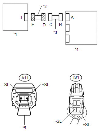
(a) Disconnect the engine room main wire connector from the instrument panel wire. HINT: The service wire has already been inserted into connector E. |
|
(b) Measure the resistance according to the value(s) in the table below.
Standard Resistance:
|
Tester Connection |
Condition |
Specified Condition |
|---|---|---|
|
IS1-3 (-SL) - IS1-4 (+SL) |
Always |
Below 1 Ω |
|
*1 |
Front Airbag Sensor LH |
|
*2 |
Engine Room Main Wire |
|
*3 |
Instrument Panel Wire |
|
*4 |
Airbag Sensor Assembly |
|
*5 |
Service Wire |
| OK | |
REPLACE INSTRUMENT PANEL WIRE |
| NG | |
REPLACE ENGINE ROOM MAIN WIRE |
|
10. |
CHECK ENGINE ROOM MAIN WIRE (FOR SHORT) |
|
(a) Disconnect the engine room main wire connector from the instrument panel wire. |
|
(b) Measure the resistance according to the value(s) in the table below.
Standard Resistance:
|
Tester Connection |
Condition |
Specified Condition |
|---|---|---|
|
IS1-3 (-SL) - IS1-4 (+SL) |
Always |
1 MΩ or Higher |
|
*1 |
Front Airbag Sensor LH |
|
*2 |
Engine Room Main Wire |
|
*3 |
Instrument Panel Wire |
|
*4 |
Airbag Sensor Assembly |
| OK | |
REPLACE INSTRUMENT PANEL WIRE |
| NG | |
REPLACE ENGINE ROOM MAIN WIRE |
|
11. |
CHECK ENGINE ROOM MAIN WIRE (TO B+) |
|
(a) Turn the ignition switch off. |
|
(b) Disconnect the negative (-) terminal cable from the battery, and wait for at least 90 seconds.
(c) Disconnect the engine room main wire connector from the instrument panel wire.
(d) Connect the negative (-) terminal cable to the battery, and wait for at least 2 seconds.
(e) Turn the ignition switch to ON.
(f) Measure the voltage according to the value(s) in the table below.
Standard Voltage:
|
Tester Connection |
Switch Condition |
Specified Condition |
|---|---|---|
|
IS1-3 (-SL) - Body ground |
Ignition switch ON |
Below 1 V |
|
IS1-4 (+SL) - Body ground |
Ignition switch ON |
Below 1 V |
|
*1 |
Front Airbag Sensor LH |
|
*2 |
Engine Room Main Wire |
|
*3 |
Instrument Panel Wire |
|
*4 |
Airbag Sensor Assembly |
| OK | |
REPLACE INSTRUMENT PANEL WIRE |
| NG | |
REPLACE ENGINE ROOM MAIN WIRE |
|
12. |
CHECK ENGINE ROOM MAIN WIRE (TO GROUND) |
|
(a) Disconnect the engine room main wire connector from the instrument panel wire. |
|
(b) Measure the resistance according to the value(s) in the table below.
Standard Resistance:
|
Tester Connection |
Condition |
Specified Condition |
|---|---|---|
|
IS1-3 (-SL) - Body ground |
Always |
1 MΩ or Higher |
|
IS1-4 (+SL) - Body ground |
Always |
1 MΩ or Higher |
|
*1 |
Front Airbag Sensor LH |
|
*2 |
Engine Room Main Wire |
|
*3 |
Instrument Panel Wire |
|
*4 |
Airbag Sensor Assembly |
| OK | |
REPLACE INSTRUMENT PANEL WIRE |
| NG | |
REPLACE ENGINE ROOM MAIN WIRE |
 Center Airbag Sensor Assembly Malfunction (B1000/31)
DESCRIPTION
The airbag sensor assembly consists of a deceleration sensor, safing sensor,
drive circuit, diagnosis circuit, ignition control, etc.
If the airbag sensor assembly receives signals fro ...
 Side Airbag Sensor RH Circuit Malfunction (B1620/21)
DESCRIPTION
The side airbag sensor assembly RH consists of parts such as the safing sensor,
the diagnostic circuit and the lateral deceleration sensor.
When the airbag sensor assembly receives sig ...
Other materials:
Front Stabilizer Bar
Components
COMPONENTS
ILLUSTRATION
Inspection
INSPECTION
PROCEDURE
1. INSPECT FRONT STABILIZER LINK ASSEMBLY
(a) Flip the ball joint stud back and forth 5 times, as shown in the illustration,
before installing the nut.
(b) Using a torque wrench, turn the nut continuously at a rate ...
Rear Power Outlet Socket
Components
COMPONENTS
ILLUSTRATION
ILLUSTRATION
Installation
INSTALLATION
PROCEDURE
1. INSTALL POWER OUTLET SOCKET ASSEMBLY
(a) Install the clamp.
(b) Connect the connector.
(c) Using a torx socket wrench T30, install the 4 screws and the power
outlet socket assemb ...
Parts Location
PARTS LOCATION
ILLUSTRATION
*A
for Automatic Transmission
*B
for Manual Transmission
*C
for 4WD
-
-
*1
FRONT SPEED SENSOR LH
*2
FRONT SPEED SENSOR RH
...
