Toyota Tacoma (2015-2018) Service Manual: Front Speed Sensor
Removal
REMOVAL
PROCEDURE
1. PRECAUTION
NOTICE:
After turning the ignition switch off, waiting time may be required before disconnecting the cable from the negative (-) battery terminal.
Therefore, make sure to read the disconnecting the cable from the negative (-) battery terminal notices before proceeding with work.
Click here .gif)
2. DISCONNECT CABLE FROM NEGATIVE BATTERY TERMINAL
NOTICE:
When disconnecting the cable, some systems need to be initialized after the cable is reconnected.
Click here
3. REMOVE FRONT WHEEL
4. REMOVE FRONT SPEED SENSOR
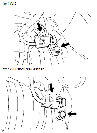
(a) Disconnect the speed sensor connector.
(b) Remove the bolt and front speed sensor.
NOTICE:
- Do not attach any foreign matter to the sensor tip.
- Ensure that no foreign matter enters the sensor installation part.
Installation
INSTALLATION
PROCEDURE
1. INSTALL FRONT SPEED SENSOR
(a) Install the front speed sensor with the bolt.
Torque:
8.3 N·m {85 kgf·cm, 73 in·lbf}
NOTICE:
Make sure that the sensor tip is clean.
(b) Connect the speed sensor connector.
2. INSTALL FRONT WHEEL
Torque:
113 N·m {1152 kgf·cm, 83 ft·lbf}
3. CONNECT CABLE TO NEGATIVE BATTERY TERMINAL
Torque:
5.4 N·m {55 kgf·cm, 48 in·lbf}
NOTICE:
When disconnecting the cable, some systems need to be initialized after the cable is reconnected.
Click here .gif)
4. CHECK VSC SENSOR SIGNAL (for Hydraulic Brake Booster)
Click here
5. CHECK VSC SENSOR SIGNAL (for Vacuum Brake Booster)
Click here
 Crawl Switch
Components
COMPONENTS
ILLUSTRATION
Inspection
INSPECTION
PROCEDURE
1. INSPECT CRAWL CONTROL SWITCH (DRIVE MONITOR SWITCH)
(a) Check the resistance.
(1) Measure the resistance according t ...
 Multi-terrain Select Switch
Components
COMPONENTS
ILLUSTRATION
Removal
REMOVAL
PROCEDURE
1. REMOVE MULTI-TERRAIN SELECT SWITCH (DRIVE MONITOR SWITCH)
(a) Disengage the 2 claws to remove the multi-terrain ...
Other materials:
Portable Player cannot be Connected Manually/Automatically
CAUTION / NOTICE / HINT
HINT:
Some versions of "Bluetooth" compatible audio players may not function, or the
function may be limited using the navigation receiver assembly, even if the portable
audio player itself can play files (See page ).
PROCEDURE
1.
CHE ...
GPS Mark is not Displayed
PROCEDURE
1.
CHECK CABIN
(a) Check the cabin for any object that might interrupt radio reception or additional
devices which use radio waves on the instrument panel. If such an object exists,
remove it and check if the GPS mark reappears.
HINT:
The GPS uses ex ...
Pump Motor Relay (C1253)
DESCRIPTION
The motor relay (semiconductor relay) is built into the master cylinder solenoid
and drives the pump motor based on a signal from the skid control ECU (master cylinder
solenoid).
DTC No.
DTC Detecting Condition
Trouble Areas
C1253
...
