Toyota Tacoma (2015-2018) Service Manual: Side Airbag Sensor RH Circuit Malfunction (B1620/21)
DESCRIPTION
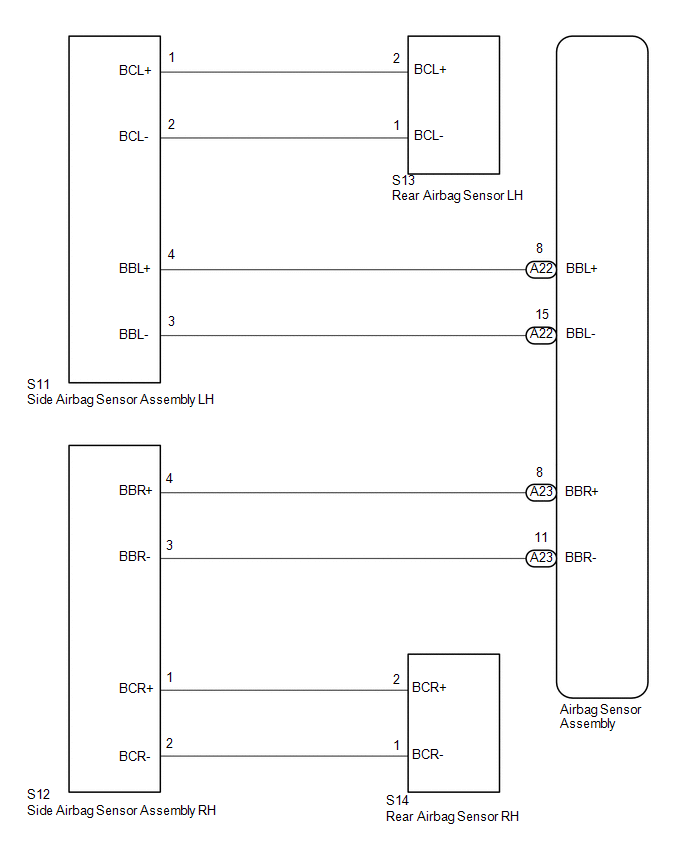
The side airbag sensor assembly RH consists of parts such as the safing sensor, the diagnostic circuit and the lateral deceleration sensor.
When the airbag sensor assembly receives signals from the lateral deceleration sensor, it determines whether or not the SRS should be activated.
DTC B1620/21 is set when a malfunction is detected in the side airbag sensor assembly RH and rear airbag sensor RH circuit.
|
DTC No. |
DTC Detecting Conditions |
Trouble Areas |
|---|---|---|
|
B1620/21 |
|
|
WIRING DIAGRAM
CAUTION / NOTICE / HINT
NOTICE:
After turning the ignition switch off, waiting time may be required before disconnecting
the cable from the negative (-) battery terminal. Therefore, make sure to read the
disconnecting the cable from the negative (-) battery terminal notices before proceeding
with work (See page .gif) ).
).
PROCEDURE
|
1. |
CHECK CONNECTION OF CONNECTORS |
(a) Turn the ignition switch off.
(b) Disconnect the negative (-) terminal cable from the battery, and wait for at least 90 seconds.
(c) Check that the connectors are properly connected to the airbag sensor assembly and the side airbag sensor assembly RH.
OK:
The connectors are properly connected.
| NG | .gif) |
CONNECT CONNECTORS |
|
.gif)
|
2. |
CHECK CONNECTORS |
(a) Check that the connectors (on the airbag sensor assembly side and side airbag
sensor assembly RH side) are not damaged (See page
).
OK:
The connectors are not deformed or damaged.
| NG | |
REPLACE WIRE HARNESS |
|
|
3. |
CHECK FLOOR WIRE (FOR OPEN) |
|
(a) Disconnect the connectors from the airbag sensor assembly and the side airbag sensor assembly RH. |
|
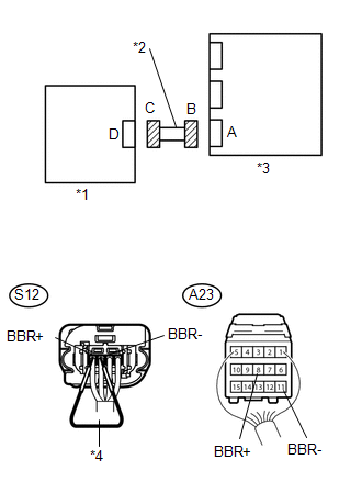
(b) Using service wire, connect S12-4 (BBR+) and S12-3 (BBR-) of connector C.
(c) Measure the resistance according to the value(s) in the table below.
Standard Resistance:
|
Tester Connection |
Condition |
Specified Condition |
|---|---|---|
|
A23-8 (BBR+) - A23-11 (BBR-) |
Always |
Below 1 Ω |
|
*1 |
Side Airbag Sensor Assembly RH |
|
*2 |
Floor Wire |
|
*3 |
Airbag Sensor Assembly |
|
*4 |
Service Wire |
| NG | |
REPLACE FLOOR WIRE |
|
|
4. |
CHECK FLOOR WIRE (FOR SHORT) |
|
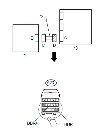
(a) Disconnect the service wire from connector C. |
|

(b) Measure the resistance according to the value(s) in the table below.
Standard Resistance:
|
Tester Connection |
Condition |
Specified Condition |
|---|---|---|
|
A23-8 (BBR+) - A23-11 (BBR-) |
Always |
1 MΩ or Higher |
|
*1 |
Side Airbag Sensor Assembly RH |
|
*2 |
Floor Wire |
|
*3 |
Airbag Sensor Assembly |
| NG | |
REPLACE FLOOR WIRE |
|
|
5. |
CHECK FLOOR WIRE (TO B+) |
|
(a) Connect the negative (-) terminal cable to the battery, and wait for at least 2 seconds. |
|
(b) Turn the ignition switch to ON.
(c) Measure the voltage according to the value(s) in the table below.
Standard Voltage:
|
Tester Connection |
Switch Condition |
Specified Condition |
|---|---|---|
|
A23-8 (BBR+) - Body ground |
Ignition switch ON |
Below 1 V |
|
A23-11 (BBR-) - Body ground |
Ignition switch ON |
Below 1 V |
|
*1 |
Side Airbag Sensor Assembly RH |
|
*2 |
Floor Wire |
|
*3 |
Airbag Sensor Assembly |
| NG | |
REPLACE FLOOR WIRE |
|
|
6. |
CHECK FLOOR WIRE (TO GROUND) |
|
(a) Turn the ignition switch off. |
|
(b) Disconnect the negative (-) terminal cable from the battery, and wait for at least 90 seconds.
(c) Measure the resistance according to the value(s) in the table below.
Standard Resistance:
|
Tester Connection |
Condition |
Specified Condition |
|---|---|---|
|
A23-8 (BBR+) - Body ground |
Always |
1 MΩ or Higher |
|
A23-11 (BBR-) - Body ground |
Always |
1 MΩ or Higher |
|
*1 |
Side Airbag Sensor Assembly RH |
|
*2 |
Floor Wire |
|
*3 |
Airbag Sensor Assembly |
| NG | |
REPLACE FLOOR WIRE |
|
|
7. |
CHECK SIDE AIRBAG SENSOR ASSEMBLY RH |
(a) Connect the connectors to the airbag sensor assembly.
(b) Interchange the side airbag sensor assembly RH with the side airbag sensor assembly LH and connect the connectors to them.
(c) Connect the negative (-) terminal cable to the battery, and wait for at least 2 seconds.
(d) Turn the ignition switch to ON, and wait for at least 60 seconds.
(e) Clear any DTCs stored in the memory (See page
).
(f) Turn the ignition switch off.
(g) Turn the ignition switch to ON, and wait for at least 60 seconds.
(h) Check for DTCs (See page ).
|
Result |
Proceed to |
|---|---|
|
DTC B1620/21 is output. |
A |
|
DTC B1625/22 is output. |
B |
|
Neither DTC B1620/21 nor B1625/22 is output. |
C |
| B | |
REPLACE REAR AIRBAG SENSOR RH |
| C | |
USE SIMULATION METHOD TO CHECK |
|
|
8. |
CHECK CONNECTION OF CONNECTORS |
(a) Turn the ignition switch off.
(b) Disconnect the negative (-) terminal cable from the battery, and wait for at least 90 seconds.
(c) Check that the connectors are properly connected to the airbag sensor assembly and the side airbag sensor assembly RH.
OK:
The connectors are properly connected.
| NG | |
CONNECT CONNECTORS |
|
|
9. |
CHECK CONNECTORS |
(a) Check that the connectors (on the side airbag sensor assembly RH side and
rear airbag sensor RH side) are not damaged (See page
).
OK:
The connectors are not deformed or damaged.
| NG | |
REPLACE WIRE HARNESS |
|
|
10. |
CHECK FLOOR WIRE (FOR OPEN) |
|
(a) Disconnect the connectors from the side airbag sensor assembly RH and the rear airbag sensor RH. |
|
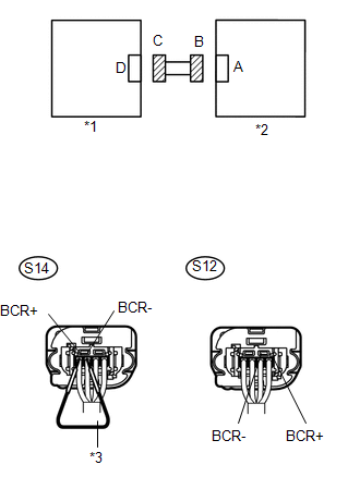
(b) Using service wire, connect S14-1 (BCR-) and S14-2 (BCR+) of connector C.
(c) Measure the resistance according to the value(s) in the table below.
Standard Resistance:
|
Tester Connection |
Condition |
Specified Condition |
|---|---|---|
|
S12-1 (BCR+) - S12-2 (BCR-) |
Always |
Below 1 Ω |
|
*1 |
Rear Airbag Sensor RH |
|
*2 |
Side Airbag Sensor Assembly RH |
|
*3 |
Service Wire |
| NG | |
REPLACE FLOOR WIRE |
|
|
11. |
CHECK FLOOR WIRE (FOR SHORT) |
|
(a) Disconnect the service wire from connector C. |
|
.png)
(b) Measure the resistance according to the value(s) in the table below.
Standard Resistance:
|
Tester Connection |
Condition |
Specified Condition |
|---|---|---|
|
S12-1 (BCR+) - S12-2 (BCR-) |
Always |
1 MΩ or Higher |
|
*1 |
Rear Airbag Sensor RH |
|
*2 |
Side Airbag Sensor Assembly RH |
| NG | |
REPLACE FLOOR WIRE |
|
|
12. |
CHECK FLOOR WIRE (TO B+) |
|
(a) Connect the negative (-) terminal cable to the battery, and wait for at least 2 seconds. |
|
(b) Turn the ignition switch to ON.
(c) Measure the voltage according to the value(s) in the table below.
Standard Voltage:
|
Tester Connection |
Switch Condition |
Specified Condition |
|---|---|---|
|
S12-1 (BCR+) - Body ground |
Ignition switch ON |
Below 1 V |
|
S12-2 (BCR-) - Body ground |
Ignition switch ON |
Below 1 V |
|
*1 |
Rear Airbag Sensor RH |
|
*2 |
Side Airbag Sensor Assembly RH |
| NG | |
REPLACE FLOOR WIRE |
|
|
13. |
CHECK FLOOR WIRE (TO GROUND) |
|
(a) Turn the ignition switch off. |
|
(b) Disconnect the negative (-) terminal cable from the battery, and wait for at least 90 seconds.
(c) Measure the resistance according to the value(s) in the table below.
Standard Resistance:
|
Tester Connection |
Condition |
Specified Condition |
|---|---|---|
|
S12-1 (BCR+) - Body ground |
Always |
1 MΩ or Higher |
|
S12-2 (BCR-) - Body ground |
Always |
1 MΩ or Higher |
|
*1 |
Rear Airbag Sensor RH |
|
*2 |
Side Airbag Sensor Assembly RH |
| NG | |
REPLACE FLOOR WIRE |
|
|
14. |
CHECK DTC |
(a) Connect the connectors to the airbag sensor assembly.
(b) Connect the negative (-) terminal cable to the battery, and wait for at least 2 seconds.
(c) Turn the ignition switch to ON, and wait for at least 60 seconds.
(d) Clear any DTCs stored in the memory (See page
).
(e) Turn the ignition switch off.
(f) Turn the ignition switch to ON, and wait for at least 60 seconds.
(g) Check for DTCs (See page ).
OK:
DTC B1620/21 is not output.
HINT:
DTCs other than B1620/21 may be output at this time, but they are not related to this check.
Result|
Result |
Proceed to |
|---|---|
|
NG |
A |
|
OK |
B |
| B | |
REPLACE REAR AIRBAG SENSOR RH |
|
|
15. |
CHECK SIDE AIRBAG SENSOR ASSEMBLY RH |
(a) Turn the ignition switch off.
(b) Disconnect the negative (-) terminal cable from the battery, and wait for at least 90 seconds.
(c) Replace the airbag sensor assembly (See page
).
HINT:
Perform the inspection using parts from a normal vehicle when possible.
(d) Connect the negative (-) terminal cable to the battery, and wait for at least 2 seconds.
(e) Turn the ignition switch to ON, and wait for at least 60 seconds.
(f) Clear any DTCs stored in the memory (See page
).
(g) Turn the ignition switch off.
(h) Turn the ignition switch to ON, and wait for at least 60 seconds.
(i) Check for DTCs (See page ).
OK:
DTC B1620/21 is not output.
HINT:
DTCs other than B1620/21 may be output at this time, but they are not related to this check.
| OK | |
END |
| NG | |
REPLACE SIDE AIRBAG SENSOR ASSEMBLY RH |
 Front Airbag Sensor LH Circuit Malfunction (B1615/14)
DESCRIPTION
The front airbag sensor LH consists of parts such as the diagnostic circuit and
the frontal detection sensor.
When the airbag sensor assembly receives signals from the frontal decelera ...
 Front Airbag Sensor RH Circuit Malfunction (B1610/13)
DESCRIPTION
The front airbag sensor RH consists of parts such as the diagnostic circuit and
the frontal detection sensor.
When the airbag sensor assembly receives signals from the frontal decelera ...
Other materials:
Parts Location
PARTS LOCATION
ILLUSTRATION
ILLUSTRATION
ILLUSTRATION
ILLUSTRATION
...
Problem Symptoms Table
PROBLEM SYMPTOMS TABLE
HINT:
Use the table below to help determine the cause of problem symptoms.
If multiple suspected areas are listed, the potential causes of the symptoms
are listed in order of probability in the "Suspected Area" column of the
table. Check each sy ...
All Doors LOCK/UNLOCK Functions do not Operate Via Door Control Switch
DESCRIPTION
The main body ECU (multiplex network body ECU) receives switch signals from the
door control switch assembly on the front passenger door and activates the door
lock motor on each door according to these signals.
WIRING DIAGRAM
PROCEDURE
1.
READ VALUE USIN ...
