Toyota Tacoma (2015-2018) Service Manual: Check Mode Procedure
CHECK MODE PROCEDURE
1. DESCRIPTION
(a) Check mode has a higher sensitivity to malfunctions and can detect malfunctions that normal mode cannot detect. Check mode can also detect all the malfunctions that normal mode can detect. In check mode, DTCs are detected with 1 trip detection logic.
2. CHECK MODE PROCEDURE
(a) Make sure that the following conditions are met:
(1) Battery positive voltage 11 V or higher.
(2) Throttle valve fully closed.
(3) Shift lever in P or N.
(4) Air conditioning off.
(b) Turn the ignition switch off.
(c) Connect the Techstream to the DLC3.
(d) Turn the ignition switch to ON.
(e) Turn the Techstream on.
(f) Enter the following menus: Powertrain / Transmission / Utility / Check Mode.
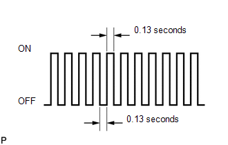
(g) Change the ECM to check mode. Make sure the MIL flashes as shown in the illustration.
NOTICE:
All DTCs and freeze frame data will be cleared if: 1) the Techstream is used to change the ECM from normal mode to check mode or vice versa; or 2) during check mode, the ignition switch is turned from ON to ACC or off.
Before entering check mode, make notes of the DTCs and freeze frame data.
(h) Start the engine. The MIL should turn off after the engine starts.
(i) Perform Monitor Drive Pattern for the ECT test (See page
.gif) ).
).
(Or, simulate the conditions of the malfunction described by the customer.)
(j) After simulating the malfunction conditions, use the Techstream to check the DTC and freeze frame data.
 Terminals Of Ecm
TERMINALS OF ECM
1. ECM
HINT:
The standard voltage between each pair of ECM terminals is shown in the table
below. In the table, first follow the information under "Condition". Look u ...
 Diagnosis System
DIAGNOSIS SYSTEM
1. DESCRIPTION
(a) When troubleshooting OBD II (On-Board Diagnostics) vehicles, an OBD II scan
tool (complying with SAE J1978) must be connected to the DLC3 (Data Link Connector
...
Other materials:
System Diagram
SYSTEM DIAGRAM
Transmitting ECU (Transmitter)
Receiving ECU
Signal
Communication Method
Skid control ECU (Brake actuator assembly)
Steering angle sensor (Spiral cable with sensor sub-assembly)
Steering angl ...
Confirm Vehicle Headunit Functionality
PROCEDURE
1.
CHECK CUSTOMER'S CELLULAR PHONE COMPATIBILITY
(a) Go to TIS "Bluetooth" Compatibility Portal and check if the cellular phone
is compatible.
Result
Result
Proceed to
Cellular phone is compatible
...
Crawl Indicator Light does not Come ON
DESCRIPTION
Refer to Crawl Indicator Light Remains ON (See page
).
WIRING DIAGRAM
Refer to Crawl Indicator Light Remains ON (See page
).
CAUTION / NOTICE / HINT
NOTICE:
When replacing the skid control ECU (master cylinder solenoid), perform
calibration (See page
).
Ins ...
