Toyota Tacoma (2015-2018) Service Manual: Parking Brake Switch Circuit
DESCRIPTION
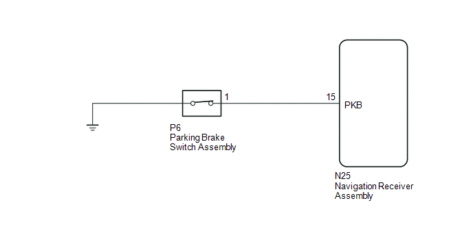
This circuit is from the parking brake switch assembly to the navigation receiver assembly.
WIRING DIAGRAM
PROCEDURE
|
1. |
CHECK VEHICLE SIGNAL (OPERATION CHECK) |
|
(a) Display the "Vehicle Signal Check Mode" screen (See page
|
|
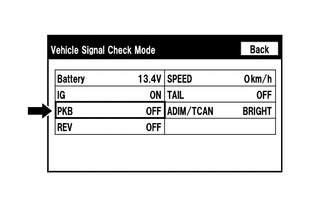
(b) Check that the display changes between ON and OFF according to the parking brake operation.
OK:
|
Parking Brake Condition |
Display |
|---|---|
|
Applied |
ON |
|
Released |
OFF |
HINT:
This display is updated once per second. As a result, it is normal for the display to lag behind the actual parking brake operation.
| OK | .gif) |
PROCEED TO NEXT SUSPECTED AREA SHOWN IN PROBLEM SYMPTOMS TABLE |
|
.gif)
|
2. |
CHECK HARNESS AND CONNECTOR (NAVIGATION RECEIVER ASSEMBLY - PARKING BRAKE SWITCH ASSEMBLY) |
(a) Disconnect the N25 navigation receiver assembly connector.
(b) Disconnect the P6 parking brake switch assembly connector.
(c) Measure the resistance according to the value(s) in the table below.
Standard Resistance:
|
Tester Connection |
Condition |
Specified Condition |
|---|---|---|
|
N25-15 (PKB) - P6-1 |
Always |
Below 1 Ω |
|
N25-15 (PKB) - Body ground |
Always |
10 kΩ or higher |
| NG | |
REPAIR OR REPLACE HARNESS OR CONNECTOR |
|
|
3. |
INSPECT PARKING BRAKE SWITCH ASSEMBLY |
(a) Remove the parking brake switch assembly.
(b) Inspect the parking brake switch assembly.
- for Hydraulic Brake Booster: See page
.gif)
- for Vacuum Brake Booster: See page
| OK | |
PROCEED TO NEXT SUSPECTED AREA SHOWN IN PROBLEM SYMPTOMS TABLE |
| NG | |
REPLACE PARKING BRAKE SWITCH ASSEMBLY |
 Illumination Circuit
DESCRIPTION
Power is supplied to the navigation receiver assembly and steering pad switch
assembly illumination when the light control switch is in the TAIL or HEAD position.
WIRING DIAGRAM
CAU ...
 Speaker Circuit
DESCRIPTION
If there is a short in a speaker circuit, the stereo component amplifier assembly*1
or navigation receiver assembly*2 detects it and stops output to the speakers.
Thus sound cannot be ...
Other materials:
Rear Body Side Panel Protector
Components
COMPONENTS
ILLUSTRATION
ILLUSTRATION
Installation
INSTALLATION
CAUTION / NOTICE / HINT
HINT:
Use the same procedure for the RH side and LH side.
The following procedure is for the LH side.
PROCEDURE
1. INSTALL REAR BODY SIDE PANEL PROTECTOR
(a) for Sho ...
Open in Outer Mirror Indicator(Slave) (C1AB5)
DESCRIPTION
This DTC is stored when the blind spot monitor sensor RH detects an open in the
blind spot monitor indicator RH.
DTC Code
DTC Detection Condition
Trouble Area
C1AB5
With the blind spot monitor main switch assembly (warning ...
Problem Symptoms Table
PROBLEM SYMPTOMS TABLE
HINT:
Use the table below to help determine the cause of problem symptoms. If multiple
suspected areas are listed, the potential causes of the symptoms are listed in order
of probability in the "Suspected Area" column of the table. Check each symptom by
check ...
