Toyota Tacoma (2015-2018) Service Manual: Washer Nozzle
Components
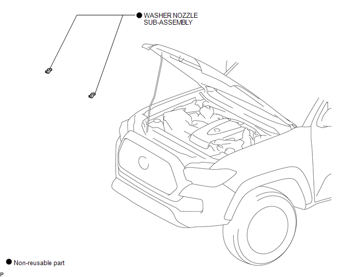
COMPONENTS
ILLUSTRATION
On-vehicle Inspection
ON-VEHICLE INSPECTION
PROCEDURE
1. INSPECT WASHER NOZZLE SUB-ASSEMBLY
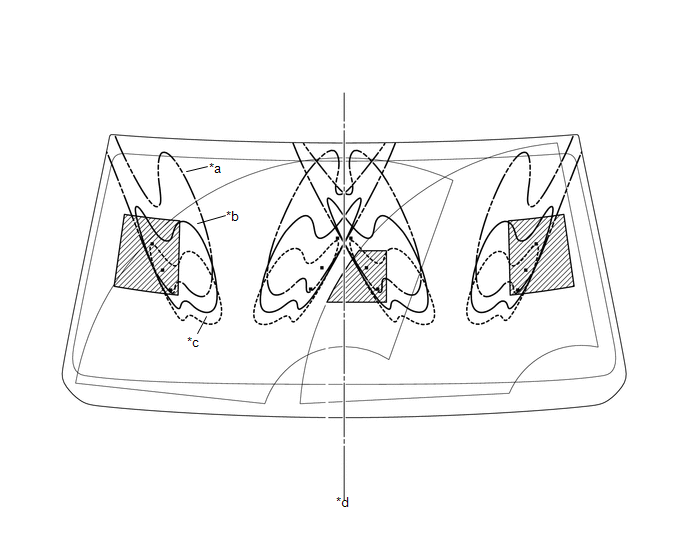
(a) Operate the washer nozzle sub-assembly and check the position that the washer fluid hits the windshield.
Standard:
Washer fluid hits the windshield glass in the areas shown in the illustration.
 Text in Illustration
|
*a |
Upper Limit |
*b |
Standard |
|
*c |
Lower Limit |
*d |
Vehicle center line |
.png) |
Reference |
- |
- |
HINT:
If the result is not as specified, replace the washer nozzle sub-assembly.
Adjustment
ADJUSTMENT
PROCEDURE
1. REMOVE WASHER NOZZLE SUB-ASSEMBLY
.gif)
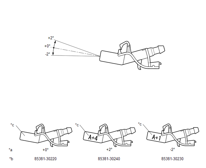
2. ADJUST WASHER NOZZLE SUB-ASSEMBLY
(a) Select a washer nozzle so that the contact area is within the standard. Replace the washer nozzle with the selected one.
 Text in Illustration
|
*a |
Washer Fluid Spray Angle |
*b |
Part Number |
|
*c |
Identification Mark |
- |
- |
3. INSTALL WASHER NOZZLE SUB-ASSEMBLY
Installation
INSTALLATION
PROCEDURE
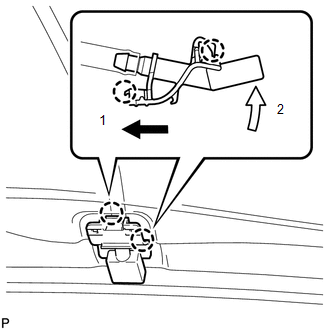
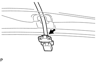
1. INSTALL WASHER NOZZLE SUB-ASSEMBLY
(a) Connect a new washer nozzle sub-assembly to the washer hose.
|
(b) Engage the 2 claws to install the washer nozzle sub-assembly as shown in the illustration. |
|
2. INSPECT WASHER NOZZLE SUB-ASSEMBLY
.gif)
3. ADJUST WASHER NOZZLE SUB-ASSEMBLY
Removal
REMOVAL
PROCEDURE
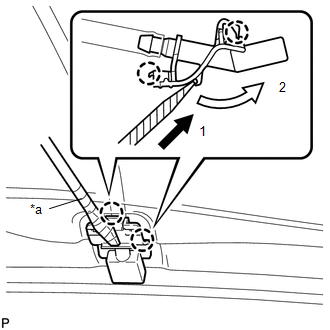
1. REMOVE WASHER NOZZLE SUB-ASSEMBLY
HINT:
Use the same procedure for both sides.
|
(a) Using a screwdriver with its tip wrapped in protective tape, disengage the 2 claws to separate the washer nozzle sub-assembly as shown in the illustration. Text in Illustration
NOTICE: Do not damage the windshield glass. |
|
|
(b) Remove the washer nozzle sub-assembly from the washer hose. NOTICE: Washer nozzle sub-assembly cannot be reused. |
|
 Washer Motor
Components
COMPONENTS
ILLUSTRATION
On-vehicle Inspection
ON-VEHICLE INSPECTION
PROCEDURE
1. INSPECT WINDSHIELD WASHER MOTOR AND PUMP ASSEMBLY
HINT:
This check should be performed with th ...

Other materials:
FCM Destination Information Uninitialized (C1AAA)
DESCRIPTION
When the forward recognition camera is replaced with a new one, the new forward
recognition camera attempts to store the country specification information received
from the main body ECU (multiplex network body ECU). If the forward recognition
camera cannot store the country speci ...
Installation
INSTALLATION
CAUTION / NOTICE / HINT
HINT:
Use the same procedure for the RH and LH sides.
The procedure listed below is for the LH side.
PROCEDURE
1. INSTALL FRONT NO. 1 SPEAKER ASSEMBLY
(a) Install the front No. 1 speaker assembly with the 4 screws.
NOTICE:
Do not touch t ...
Cruise Control Switch Circuit
DESCRIPTION
The cruise control main switch is used to turn the dynamic radar cruise control
system on and off, as well as operate 7 functions: SET, - (COAST), TAP-DOWN, RES
(RESUME), + (ACCEL), TAP-UP and CANCEL.
The SET, TAP-DOWN and - (COAST) functions, and the RES (RESUME), TAP-UP and +
( ...
