Toyota Tacoma (2015-2018) Service Manual: Speaker Circuit
DESCRIPTION
If there is a short in a speaker circuit, the stereo component amplifier assembly*1 or navigation receiver assembly*2 detects it and stops output to the speakers.
Thus sound cannot be heard from the speakers even if there is no malfunction in the stereo component amplifier assembly*1 or navigation receiver assembly*2 or speakers.
If a short is detected in a speaker circuit, no sound can be heard from the speakers.
*1: w/ Stereo Component Amplifier
*2: w/o Stereo Component Amplifier
WIRING DIAGRAM
(See page .gif) )
)
PROCEDURE
|
1. |
CONFIRM MODEL |
(a) Choose the model to be inspected.
Result|
Result |
Proceed to |
|---|---|
|
w/o Stereo Component Amplifier |
A |
|
w/ Stereo Component Amplifier |
B |
| B | .gif) |
GO TO STEP 9 |
|
.gif)
|
2. |
CHECK SPEAKER (OPERATION CHECK) |
|
(a) Enter the "System Check Mode" screen. Refer to Check Speaker in Operation Check (See page
|
|
.png)
(b) Perform the operation check above and determine the speaker that is not operating.
Result|
Not Operating Speaker |
Proceed to |
|---|---|
|
Front No. 1 speaker assembly or front No. 2 speaker assembly |
A |
|
Rear speaker assembly |
B |
HINT:
If sound cannot be heard from any speaker, inspect all of them.
| B | |
GO TO STEP 7 |
|
|
3. |
CHECK HARNESS AND CONNECTOR (NAVIGATION RECEIVER ASSEMBLY - FRONT NO. 2 SPEAKER ASSEMBLY - FRONT NO. 1 SPEAKER ASSEMBLY) |
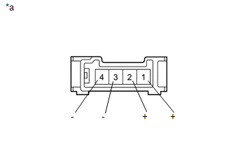
(a) Disconnect the N24 navigation receiver assembly connector.
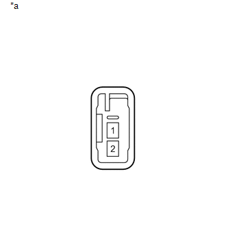
(b) Disconnect the S46 and S47 front No. 2 speaker assembly connectors.
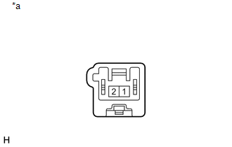
(c) Disconnect the S15 and S16 front No. 1 speaker assembly connectors.
(d) Measure the resistance between the navigation receiver assembly and each of the front No. 2 speaker assemblies to check for an open circuit in the wire harness.
Standard Resistance:
|
Tester Connection |
Condition |
Specified Condition |
|---|---|---|
|
N24-1 (FR+) - S47-2 (+) |
Always |
Below 1 Ω |
|
N24-5 (FR-) - S47-4 (-) |
Always |
Below 1 Ω |
|
N24-2 (FL+) - S46-2 (+) |
Always |
Below 1 Ω |
|
N24-6 (FL-) - S46-4 (-) |
Always |
Below 1 Ω |
(e) Measure the resistance between each of the front No. 2 speaker assemblies and the front No. 1 speaker assemblies to check for an open circuit in the wire harness.
Standard Resistance:
|
Tester Connection |
Condition |
Specified Condition |
|---|---|---|
|
S46-1 (+) - S15-1 |
Always |
Below 1 Ω |
|
S46-3 (-) - S15-2 |
Always |
Below 1 Ω |
|
S47-1 (+) - S16-1 |
Always |
Below 1 Ω |
|
S47-3 (-) - S16-2 |
Always |
Below 1 Ω |
(f) Measure the resistance between the navigation receiver assembly and body ground to check for a short circuit in the wire harness.
Standard Resistance:
|
Tester Connection |
Condition |
Specified Condition |
|---|---|---|
|
N24-1 (FR+) - Body ground |
Always |
10 kΩ or higher |
|
N24-5 (FR-) - Body ground |
Always |
10 kΩ or higher |
|
N24-2 (FL+) - Body ground |
Always |
10 kΩ or higher |
|
N24-6 (FL-) - Body ground |
Always |
10 kΩ or higher |
(g) Measure the resistance between each of the front No. 2 speaker assemblies and body ground to check for a short circuit in the wire harness.
Standard Resistance:
|
Tester Connection |
Condition |
Specified Condition |
|---|---|---|
|
S46-1 (+) - Body ground |
Always |
10 kΩ or higher |
|
S46-3 (-) - Body ground |
Always |
10 kΩ or higher |
|
S47-1 (+) - Body ground |
Always |
10 kΩ or higher |
|
S47-3 (-) - Body ground |
Always |
10 kΩ or higher |
| NG | |
REPAIR OR REPLACE HARNESS OR CONNECTOR |
|
|
4. |
INSPECT FRONT NO. 2 SPEAKER ASSEMBLY |
(a) Remove the front No. 2 speaker assembly (See page
).
|
(b) Measure the resistance according to the value(s) in the table below. Standard Resistance:
|
|
| NG | |
REPLACE FRONT NO. 1 SPEAKER ASSEMBLY |
|
|
5. |
REPLACE FRONT NO. 2 SPEAKER ASSEMBLY |
(a) Check that the malfunction disappears when a known good speaker is installed
(See page ).
OK:
Malfunction disappears.
HINT:
- Connect all the connectors to the front No. 2 speaker assemblies that were disconnected.
- When there is a possibility that either the right or left front No. 2 speaker assembly is defective, inspect by interchanging the right one with the left one.
- Perform the above inspection on both the LH and RH side.
| OK | |
END |
|
|
6. |
INSPECT FRONT NO. 1 SPEAKER ASSEMBLY |
(a) Remove the front No. 1 speaker assembly (See page
).
|
(b) Measure the resistance according to the value(s) in the table below. Standard Resistance:
|
|
.png)
| OK | |
PROCEED TO NEXT SUSPECTED AREA SHOWN IN PROBLEM SYMPTOMS TABLE |
| NG | |
REPLACE FRONT NO. 1 SPEAKER ASSEMBLY |
|
7. |
CHECK HARNESS AND CONNECTOR (NAVIGATION RECEIVER ASSEMBLY - REAR SPEAKER ASSEMBLY) |
(a) Disconnect the N23 navigation receiver assembly connector.
(b) Disconnect the S17 and S18 rear speaker assembly connectors.
(c) Measure the resistance between the navigation receiver assembly and each of the rear speaker assemblies to check for an open circuit in the wire harness.
Standard Resistance:
|
Tester Connection |
Condition |
Specified Condition |
|---|---|---|
|
N23-1 (RR+) - S18-1 |
Always |
Below 1 Ω |
|
N23-3 (RR-) - S18-2 |
Always |
Below 1 Ω |
|
N23-2 (RL+) - S17-1 |
Always |
Below 1 Ω |
|
N23-6 (RL-) - S17-2 |
Always |
Below 1 Ω |
(d) Measure the resistance between the navigation receiver assembly and body ground to check for a short circuit in the wire harness.
Standard Resistance:
|
Tester Connection |
Condition |
Specified Condition |
|---|---|---|
|
N23-1 (RR+) - Body ground |
Always |
10 kΩ or higher |
|
N23-3 (RR-) - Body ground |
Always |
10 kΩ or higher |
|
N23-2 (RL+) - Body ground |
Always |
10 kΩ or higher |
|
N23-6 (RL-) - Body ground |
Always |
10 kΩ or higher |
| NG | |
REPAIR OR REPLACE HARNESS OR CONNECTOR |
|
|
8. |
INSPECT REAR SPEAKER ASSEMBLY |
(a) Remove the rear speaker assembly (See page
).
|
(b) Measure the resistance according to the value(s) in the table below. Standard Resistance:
|
|
| OK | |
PROCEED TO NEXT SUSPECTED AREA SHOWN IN PROBLEM SYMPTOMS TABLE |
| NG | |
REPLACE REAR SPEAKER ASSEMBLY |
|
9. |
CHECK SPEAKER (OPERATION CHECK) |
|
(a) Enter the "System Check Mode" screen. Refer to Check Speaker in Operation Check (See page
|
|
(b) Perform the operation check above and determine the speaker that is not operating.
Result|
Not Operating Speaker |
Proceed to |
|---|---|
|
Front No. 1 speaker assembly |
A |
|
Front No. 2 speaker assembly |
B |
|
No. 1 speaker assembly with box |
C |
|
Rear speaker assembly |
D |
HINT:
If sound cannot be heard from any speaker, inspect all of them.
| B | |
GO TO STEP 12 |
| C | |
GO TO STEP 14 |
| D | |
GO TO STEP 16 |
|
|
10. |
CHECK HARNESS AND CONNECTOR (STEREO COMPONENT AMPLIFIER ASSEMBLY - FRONT NO. 1 SPEAKER ASSEMBLY) |
(a) Disconnect the S24 stereo component amplifier assembly connector.
(b) Disconnect the S15 and S16 front No. 1 speaker assembly connectors.
(c) Measure the resistance between the stereo component amplifier assembly and each of the front No. 1 speaker assemblies to check for an open circuit in the wire harness.
Standard Resistance:
|
Tester Connection |
Condition |
Specified Condition |
|---|---|---|
|
S24-9 (FR+) - S16-1 |
Always |
Below 1 Ω |
|
S24-3 (FR-) - S16-2 |
Always |
Below 1 Ω |
|
S24-2 (FL+) - S15-1 |
Always |
Below 1 Ω |
|
S24-1 (FL-) - S15-2 |
Always |
Below 1 Ω |
(d) Measure the resistance between the stereo component amplifier assembly and body ground to check for a short circuit in the wire harness.
Standard Resistance:
|
Tester Connection |
Condition |
Specified Condition |
|---|---|---|
|
S24-9 (FR+) - Body ground |
Always |
10 kΩ or higher |
|
S24-3 (FR-) - Body ground |
Always |
10 kΩ or higher |
|
S24-2 (FL+) - Body ground |
Always |
10 kΩ or higher |
|
S24-1 (FL-) - Body ground |
Always |
10 kΩ or higher |
| NG | |
REPAIR OR REPLACE HARNESS OR CONNECTOR |
|
|
11. |
INSPECT FRONT NO. 1 SPEAKER ASSEMBLY |
(a) Remove the front No. 1 speaker assembly (See page
).
|
(b) Measure the resistance according to the value(s) in the table below. Standard Resistance:
|
|
| OK | |
PROCEED TO NEXT SUSPECTED AREA SHOWN IN PROBLEM SYMPTOMS TABLE |
| NG | |
REPLACE FRONT NO. 1 SPEAKER ASSEMBLY |
|
12. |
CHECK HARNESS AND CONNECTOR (STEREO COMPONENT AMPLIFIER ASSEMBLY - FRONT NO. 2 SPEAKER ASSEMBLY) |
(a) Disconnect the S31 stereo component amplifier assembly connector.
(b) Disconnect the S48 and S49 front No. 2 speaker assembly connectors.
(c) Measure the resistance between the stereo component amplifier assembly and each of the front No. 2 speaker assemblies to check for an open circuit in the wire harness.
Standard Resistance:
|
Tester Connection |
Condition |
Specified Condition |
|---|---|---|
|
S31-2 (TWR+) - S49-2 |
Always |
Below 1 Ω |
|
S31-6 (TWR-) - S49-1 |
Always |
Below 1 Ω |
|
S31-8 (TWL+) - S48-2 |
Always |
Below 1 Ω |
|
S31-7 (TWL-) - S48-1 |
Always |
Below 1 Ω |
(d) Measure the resistance between the stereo component amplifier assembly and body ground to check for a short circuit in the wire harness.
Standard Resistance:
|
Tester Connection |
Condition |
Specified Condition |
|---|---|---|
|
S31-2 (TWR+) - Body ground |
Always |
10 kΩ or higher |
|
S31-6 (TWR-) - Body ground |
Always |
10 kΩ or higher |
|
S31-8 (TWL+) - Body ground |
Always |
10 kΩ or higher |
|
S31-7 (TWL-) - Body ground |
Always |
10 kΩ or higher |
| NG | |
REPAIR OR REPLACE HARNESS OR CONNECTOR |
|
|
13. |
INSPECT FRONT NO. 2 SPEAKER ASSEMBLY |
(a) Remove the front No. 2 speaker assembly (See page
).
|
(b) Measure the resistance according to the value(s) in the table below. Standard Resistance:
|
|
| OK | |
PROCEED TO NEXT SUSPECTED AREA SHOWN IN PROBLEM SYMPTOMS TABLE |
| NG | |
REPLACE FRONT NO. 1 SPEAKER ASSEMBLY |
|
14. |
CHECK HARNESS AND CONNECTOR (STEREO COMPONENT AMPLIFIER ASSEMBLY - NO. 1 SPEAKER ASSEMBLY WITH BOX) |
(a) Disconnect the S24 stereo component amplifier assembly connector.
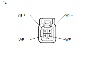
(b) Disconnect the S21 No. 1 speaker assembly with box connectors.
(c) Measure the resistance between the stereo component amplifier assembly and each of the No. 1 speaker assembly with box to check for an open circuit in the wire harness.
Standard Resistance:
|
Tester Connection |
Condition |
Specified Condition |
|---|---|---|
|
S24-4 (WFR+) - S21-1 (WF+) |
Always |
Below 1 Ω |
|
S24-10 (WFR-) - S21-4 (WF-) |
Always |
Below 1 Ω |
|
S24-5 (WFL+) - S21-2 (WF+) |
Always |
Below 1 Ω |
|
S24-12 (WFL-) - S21-3 (WF-) |
Always |
Below 1 Ω |
(d) Measure the resistance between the stereo component amplifier assembly and body ground to check for a short circuit in the wire harness.
Standard Resistance:
|
Tester Connection |
Condition |
Specified Condition |
|---|---|---|
|
S21-2 (WF+) - Body ground |
Always |
10 kΩ or higher |
|
S21-3 (WF-) - Body ground |
Always |
10 kΩ or higher |
|
S21-1 (WF+) - Body ground |
Always |
10 kΩ or higher |
|
S21-4 (WF-) - Body ground |
Always |
10 kΩ or higher |
| NG | |
REPAIR OR REPLACE HARNESS OR CONNECTOR |
|
|
15. |
INSPECT NO. 1 SPEAKER ASSEMBLY WITH BOX |
(a) Remove the rear No. 1 speaker assembly with box (See page
).
|
(b) Measure the resistance according to the value(s) in the table below. Standard Resistance:
|
|
| OK | |
PROCEED TO NEXT SUSPECTED AREA SHOWN IN PROBLEM SYMPTOMS TABLE |
| NG | |
REPLACE NO.1 SPEAKER ASSEMBLY WITH BOX |
|
16. |
CHECK HARNESS AND CONNECTOR (STEREO COMPONENT AMPLIFIER ASSEMBLY - REAR SPEAKER ASSEMBLY) |
(a) Disconnect the S31 stereo component amplifier assembly connector.
(b) Disconnect the S17 and S18 rear speaker assembly connector.
(c) Measure the resistance between the stereo component amplifier assembly and the rear speaker assembly to check for an open circuit in the wire harness.
Standard Resistance:
|
Tester Connection |
Condition |
Specified Condition |
|---|---|---|
|
S31-3 (RL+) - S17-1 |
Always |
Below 1 Ω |
|
S31-9 (RL-) - S17-2 |
Always |
Below 1 Ω |
|
S31-10 (RR+) - S18-1 |
Always |
Below 1 Ω |
|
S31-4 (RR-) - S18-2 |
Always |
Below 1 Ω |
(d) Measure the resistance between the stereo component amplifier assembly and body ground to check for a short circuit in the wire harness.
Standard Resistance:
|
Tester Connection |
Condition |
Specified Condition |
|---|---|---|
|
S31-3 (RL+) - Body ground |
Always |
10 kΩ or higher |
|
S31-9 (RL-) - Body ground |
Always |
10 kΩ or higher |
|
S31-10 (RR+) - Body ground |
Always |
10 kΩ or higher |
|
S31-4 (RR-) - Body ground |
Always |
10 kΩ or higher |
| NG | |
REPAIR OR REPLACE HARNESS OR CONNECTOR |
|
|
17. |
INSPECT REAR SPEAKER ASSEMBLY |
(a) Remove the rear speaker assembly (See page
).
|
(b) Measure the resistance according to the value(s) in the table below. Standard Resistance:
|
|

| OK | |
PROCEED TO NEXT SUSPECTED AREA SHOWN IN PROBLEM SYMPTOMS TABLE |
| NG | |
REPLACE REAR SPEAKER ASSEMBLY |
 Parking Brake Switch Circuit
DESCRIPTION
This circuit is from the parking brake switch assembly to the navigation receiver
assembly.
WIRING DIAGRAM
PROCEDURE
1.
CHECK VEHICLE SIGNAL (OPERATION CHECK ...
 Sound Signal Circuit between Radio Receiver and Stereo Component Amplifier
DESCRIPTION
The navigation receiver assembly sends a sound signal to the stereo component
amplifier assembly via this circuit.
The sound signal that has been sent is amplified by the stereo compon ...
Other materials:
Precaution
PRECAUTION
1. EXPRESSIONS OF IGNITION SWITCH
HINT:
The type of ignition switch used on this model differs according to the specifications
of the vehicle. The expressions listed in the table below are used in this section.
Expression
Ignition Switch
(Position)
...
Air Fuel Ratio Sensor
Components
COMPONENTS
ILLUSTRATION
Removal
REMOVAL
PROCEDURE
1. REMOVE AIR FUEL RATIO SENSOR (for Bank 1 Sensor 1)
(a) Disconnect the air fuel ratio sensor connector.
(b) Disengage the clamp to separate the air fuel ratio sensor wire ...
Front Speed Sensor RH Performance (C1409,C1410)
DESCRIPTION
Refer to DTCs C1401 and C1402 (See page ).
DTC Code
DTC Detection Condition
Trouble Area
C1409
C1410
One of the following conditions is met:
When the vehicle is driven in reverse at a speed of 3 km/h (2
...
