Toyota Tacoma (2015-2018) Service Manual: Illumination Circuit
DESCRIPTION
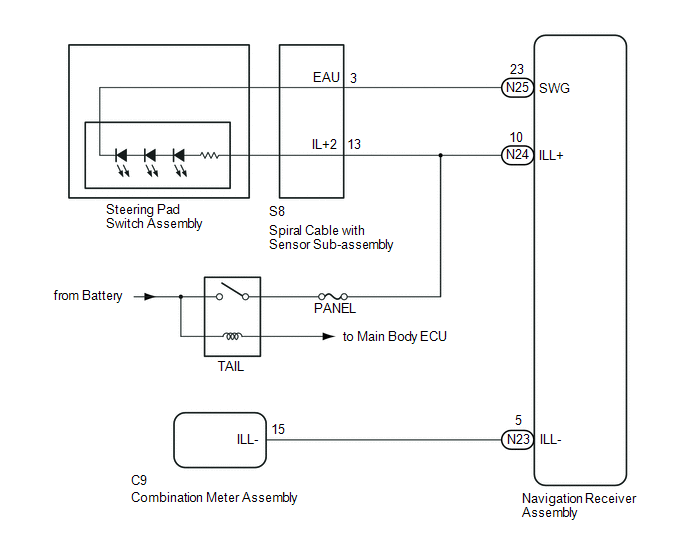
Power is supplied to the navigation receiver assembly and steering pad switch assembly illumination when the light control switch is in the TAIL or HEAD position.
WIRING DIAGRAM
CAUTION / NOTICE / HINT
NOTICE:
- The vehicle is equipped with a Supplemental Restraint System (SRS) which
includes components such as airbags. Before servicing (including removal
or installation of parts), be sure to read the precautionary notice for
the Supplemental Restraint System (See page
.gif) ).
). - Inspect the fuses for circuits related to this system before performing the following inspection procedure.
PROCEDURE
|
1. |
CHECK ILLUMINATION |
(a) Check if the illumination for the navigation receiver assembly, steering pad switch, heater control switch or others (hazard switch, transmission control switch, etc.) comes on when the light control switch is turned to the TAIL or HEAD position.
Result|
Result |
Proceed to |
|---|---|
|
Illumination comes on for all components except steering pad switch assembly |
A |
|
Illumination comes on for all components except navigation receiver assembly |
B |
|
Illumination comes on for all components except steering pad switch assembly and navigation receiver assembly |
C |
| B | .gif) |
GO TO STEP 6 |
| C | |
GO TO STEP 7 |
|
.gif)
|
2. |
CHECK HARNESS AND CONNECTOR (SPIRAL CABLE WITH SENSOR SUB-ASSEMBLY - BATTERY) |
|
(a) Disconnect the spiral cable with sensor sub-assembly connector. |
|
(b) Measure the voltage according to the value(s) in the table below.
Standard Voltage:
|
Tester Connection |
Switch Condition |
Specified Condition |
|---|---|---|
|
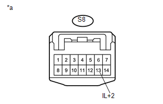
S8-13 (IL+2) - Body ground |
Light control switch in the tail or head position |
11 to 14 V |
|
*a |
Front view of wire harness connector (to Spiral Cable with Sensor Sub-assembly) |
| NG | |
REPAIR OR REPLACE HARNESS OR CONNECTOR |
|
|
3. |
INSPECT STEERING PAD SWITCH ASSEMBLY |
(a) Remove the steering pad switch assembly (See page
).
(b) Inspect the steering pad switch assembly (See page
).
| NG | |
REPLACE STEERING PAD SWITCH ASSEMBLY |
|
|
4. |
INSPECT SPIRAL CABLE WITH SENSOR SUB-ASSEMBLY |
(a) Remove the spiral cable with sensor sub-assembly (See page
).
(b) Inspect the spiral cable with sensor sub-assembly (See page
).
| NG | |
REPLACE SPIRAL CABLE WITH SENSOR SUB-ASSEMBLY |
|
|
5. |
CHECK HARNESS AND CONNECTOR (SPIRAL CABLE WITH SENSOR SUB-ASSEMBLY - NAVIGATION RECEIVER ASSEMBLY) |
(a) Disconnect the S8 spiral cable with sensor sub-assembly connector.
(b) Disconnect the N25 navigation receiver assembly connector.
(c) Measure the resistance according to the value(s) in the table below.
Standard Resistance:
|
Tester Connection |
Condition |
Specified Condition |
|---|---|---|
|
N25-23 (SWG) - S8-3 (EAU) |
Always |
Below 1 Ω |
|
N25-23 (SWG) - Body ground |
Always |
10 kΩ or higher |
| OK | |
PROCEED TO NEXT SUSPECTED AREA SHOWN IN PROBLEM SYMPTOMS TABLE |
| NG | |
REPAIR OR REPLACE HARNESS OR CONNECTOR |
|
6. |
CHECK HARNESS AND CONNECTOR (NAVIGATION RECEIVER ASSEMBLY - BATTERY) |
|
(a) Disconnect the navigation receiver assembly connector. |
|
(b) Measure the voltage according to the value(s) in the table below.
Standard Voltage:
|
Tester Connection |
Switch Condition |
Specified Condition |
|---|---|---|
|
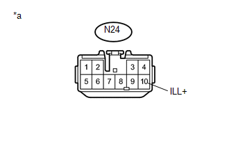
N24-10 (ILL+) - Body ground |
Light control switch in the tail or head position |
11 to 14 V |
|
*a |
Front view of wire harness connector (to Navigation Receiver Assembly) |
| NG | |
REPAIR OR REPLACE HARNESS OR CONNECTOR |
|
|
7. |
CHECK HARNESS AND CONNECTOR (NAVIGATION RECEIVER ASSEMBLY - COMBINATION METER ASSEMBLY) |
(a) Disconnect the N23 navigation receiver assembly connector.
(b) Disconnect the C9 combination meter assembly connector.
(c) Measure the resistance according to the value(s) in the table below.
Standard Resistance:
|
Tester Connection |
Condition |
Specified Condition |
|---|---|---|
|
N23-5 (ILL-) - C9-15 (ILL-) |
Always |
Below 1 Ω |
|
N23-5 (ILL-) - Body ground |
Always |
10 kΩ or higher |
| OK | |
PROCEED TO NEXT SUSPECTED AREA SHOWN IN PROBLEM SYMPTOMS TABLE |
| NG | |
REPAIR OR REPLACE HARNESS OR CONNECTOR |
 Vehicle Speed Signal Circuit between Radio Receiver and Combination Meter
DESCRIPTION
for Navigation Function:
The navigation receiver assembly receives a vehicle speed signal from
the combination meter assembly and sends the signal to navigation receiver
...
 Parking Brake Switch Circuit
DESCRIPTION
This circuit is from the parking brake switch assembly to the navigation receiver
assembly.
WIRING DIAGRAM
PROCEDURE
1.
CHECK VEHICLE SIGNAL (OPERATION CHECK ...
Other materials:
Precaution
PRECAUTION
1. INITIALIZATION
NOTICE:
If the ECM is replaced, register the ECU communication ID for Engine
Immobiliser System (See page ).
Perform Registration (VIN registration) when replacing the ECM (See
page ).
HINT:
The engine learned value cannot be rese ...
Cruise Control System Internal Failure (P057504,P057549)
DESCRIPTION
This is output when the ECM detects malfunctions in the internal circuit.
DTC Code
DTC Detection Condition
Trouble Area
MIL
Note
P057504
Vehicle Condition:
Cruise control in operation
...
Open in Pump Motor Circuit (C1251)
DESCRIPTION
The motor relay (semiconductor relay) is built into the master cylinder solenoid
and drives the pump motor based on a signal from the skid control ECU (master cylinder
solenoid).
DTC No.
DTC Detecting Condition
Trouble Areas
C1251
...
