Toyota Tacoma (2015-2018) Service Manual: Personal Light Assembly
Components
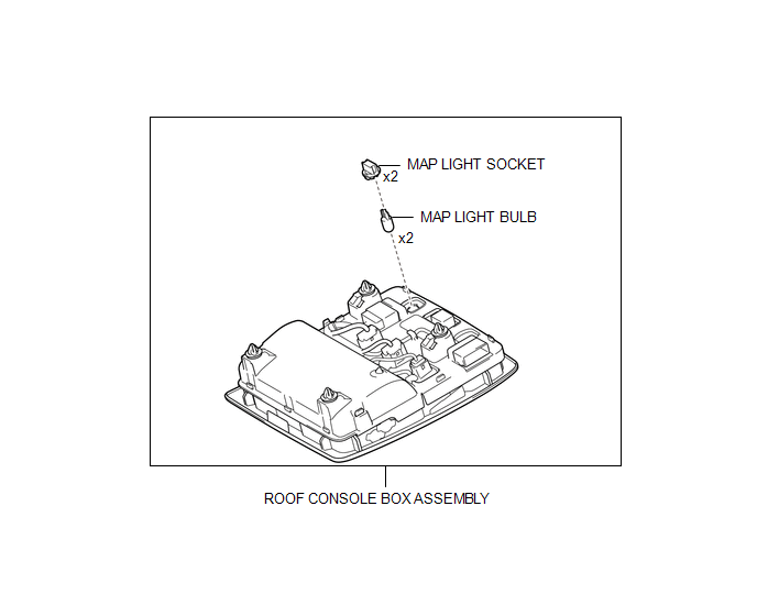
COMPONENTS
ILLUSTRATION
Installation
INSTALLATION
PROCEDURE
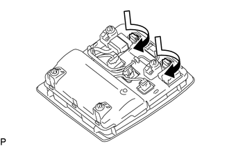
1. INSTALL MAP LIGHT BULB
(a) Install the 2 map light bulbs to the 2 map light sockets.
|
(b) Turn the 2 map light sockets with 2 map light bulbs in the direction indicated by the arrow shown in the illustration to install them |
|
2. INSTALL ROOF CONSOLE BOX ASSEMBLY
(a) Connect the connector.
(b) Engage the 4 clips to install the roof console box assembly.
Removal
REMOVAL
PROCEDURE
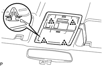
1. REMOVE ROOF CONSOLE BOX ASSEMBLY
|
(a) Using a moulding remover D, disengage the 4 clips to separate the roof console box assembly. |
|
(b) Disconnect the connector to remove the roof console box assembly.
2. REMOVE MAP LIGHT BULB
|
(a) Turn the 2 map light sockets with the 2 map light bulbs in the direction indicated by the arrow shown in the illustration to remove them. |
|
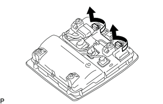
(b) Remove the map light bulb from the map light socket.
 Low Beam Headlight Circuit
DESCRIPTION
The main body ECU (multiplex network body ECU) controls the low beam headlights.
WIRING DIAGRAM
CAUTION / NOTICE / HINT
NOTICE:
Inspect the fuses for circuits related to thi ...
 Rear Combination Light Assembly
Components
COMPONENTS
ILLUSTRATION
Disassembly
DISASSEMBLY
CAUTION / NOTICE / HINT
HINT:
Use the same procedure for both the LH and RH sides.
The procedure described below is ...
Other materials:
Definition Of Terms
DEFINITION OF TERMS
Term
Definition
Monitor description
Description of what the ECM monitors and how it detects malfunctions
(monitoring purpose and details).
Related DTCs
Group of diagnostic trouble codes that are ou ...
Software Incompatibility with Body Control Module "B" (U1331)
DESCRIPTION
This DTC is stored when the destination information of the main body ECU (multiplex
network body ECU) does not match that of the blind spot monitor sensors.
DTC Code
DTC Detection Condition
Trouble Area
U1331
Destination in ...
Speed Signal Malfunction (B15C2)
DESCRIPTION
The navigation receiver assembly receives a vehicle speed signal from the combination
meter assembly and information from the navigation antenna assembly, and then adjusts
the vehicle position.
The navigation receiver assembly stores this DTC when the difference between
the speed ...
