Toyota Tacoma (2015-2018) Service Manual: Turn Signal Switch Circuit
DESCRIPTION
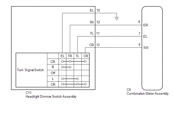
The combination meter assembly receives the turn signal switch information and controls the turn signal lights.
WIRING DIAGRAM
PROCEDURE
|
1. |
READ VALUE USING TECHSTREAM (TURN SIGNAL SWITCH) |
(a) Connect the Techstream to the DLC3.
(b) Turn the ignition switch to ON.
(c) Turn the Techstream on.
(d) Enter the following menus: Body Electrical / Combination Meter / Data List.
(e) According to the display on the Techstream, read the Data List.
Combination Meter|
Tester Display |
Measurement Item/Range |
Normal Condition |
Diagnostic Note |
|---|---|---|---|
|
Turn Signal Switch (Right) |
Turn signal switch (right) signal / ON or OFF |
ON: Turn signal switch (right) on OFF: Turn signal switch (right) off |
- |
|
Turn Signal Switch (Left) |
Turn signal switch (left) signal / ON or OFF |
ON: Turn signal switch (left) on OFF: Turn signal switch (left) off |
- |
|
Turn Switch Signal (Full Turn) |
Turn signal switch (full turn) signal / ON or OFF |
ON: Turn signal switch (left or right) on OFF: Turn signal switch (left and right) off |
- |
OK:
Normal conditions listed above are displayed.
| OK | .gif) |
PROCEED TO NEXT SUSPECTED AREA SHOWN IN PROBLEM SYMPTOMS TABLE |
|
.gif)
|
2. |
INSPECT HEADLIGHT DIMMER SWITCH ASSEMBLY |
|
(a) Remove the C11 headlight dimmer switch assembly. |
|
(b) Measure the resistance according to the value(s) in the table below.
Standard Resistance:
|
Tester Connection |
Condition |
Specified Condition |
|---|---|---|
|
12 (TR) - 15 (EL) |
Turn signal switch in neutral position |
10 kΩ or higher |
|
11 (TL) - 15 (EL) |
Turn signal switch in neutral position |
10 kΩ or higher |
|
13 (CR) - 15 (EL) |
Turn signal switch in neutral position |
10 kΩ or higher |
|
12 (TR) - 15 (EL) |
Turn signal switch in right turn position |
Below 1 Ω |
|
13 (CR) - 15 (EL) |
Turn signal switch in full right turn position |
Below 1 Ω |
|
11 (TL) - 15 (EL) |
Turn signal switch in left turn position |
Below 1 Ω |
|
13 (CR) - 15 (EL) |
Turn signal switch in full left turn position |
Below 1 Ω |
|
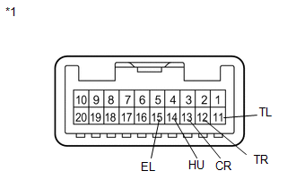
*1 |
Component without harness connected (Headlight Dimmer Switch Assembly) |
| NG | |
REPLACE HEADLIGHT DIMMER SWITCH ASSEMBLY |
|
|
3. |
CHECK HARNESS AND CONNECTOR (HEADLIGHT DIMMER SWITCH ASSEMBLY - COMBINATION METERASSEMBLY AND BODY GROUND) |
(a) Disconnect the C9 combination meter assembly connector.
(b) Disconnect the C11 headlight dimmer switch assembly connector.
(c) Measure the resistance according to the value(s) in the table below.
Standard Resistance:
|
Tester Connection |
Condition |
Specified Condition |
|---|---|---|
|
C11-12 (TR) - C9-8 (ER) |
Always |
Below 1 Ω |
|
C11-11 (TL) - C9-7 (EL) |
Always |
Below 1 Ω |
|
C11-13 (CR) - C9-9 (SW) |
Always |
Below 1 Ω |
|
C11-12 (TR) - Body ground |
Always |
10 kΩ or higher |
|
C11-11 (TL) - Body ground |
Always |
10 kΩ or higher |
|
C11-13 (CR) - Body ground |
Always |
10 kΩ or higher |
|
C11-15 (EL) - Body ground |
Always |
Below 1 Ω |
| OK | |
PROCEED TO NEXT SUSPECTED AREA SHOWN IN PROBLEM SYMPTOMS TABLE |
| NG | |
REPAIR OR REPLACE HARNESS OR CONNECTOR |
 IG Signal Circuit
DESCRIPTION
This circuit detects whether the ignition switch is ON or off, and sends this
information to the main body ECU (multiplex network body ECU).
WIRING DIAGRAM
CAUTION / NOTICE / HINT
...
 ACC Signal Circuit
DESCRIPTION
This circuit detects whether the ignition switch is ACC or off, and sends this
information to the main body ECU (multiplex network body ECU).
WIRING DIAGRAM
CAUTION / NOTICE / HINT
...
Other materials:
Front Radar Sensor Incorrect Axial Gap (C1A11,C1A14)
DESCRIPTION
When the system determines that the vehicle is driving straight ahead based on
signals from the yaw rate and acceleration sensor (airbag sensor assembly), etc.,
the millimeter wave radar sensor assembly performs self-diagnosis to check if the
sensor beam axis is misaligned.
C1A11 ...
Freeze Frame Data
FREEZE FRAME DATA
1. CHECK FREEZE FRAME DATA
(a) Connect the Techstream to the DLC3.
(b) Turn the ignition switch to ON.
(c) Turn the Techstream on.
(d) Enter the following menus: Body Electrical / Navigation System / Trouble
Codes.
(e) Select a PTC to display its Freeze Frame Data.
2. LIST ...
If your vehicle overheats
The following may indicate that your vehicle is overheating.
● The needle of the engine coolant temperature gauge (→P. 155) enters the red
zone or a loss of engine power is experienced.
(For example, the vehicle speed does not increase.) ● Steam comes out from under
the hood. ...
