Toyota Tacoma (2015-2018) Service Manual: Vacuum Warning Switch
Components
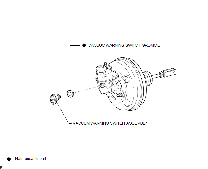
COMPONENTS
ILLUSTRATION
On-vehicle Inspection
ON-VEHICLE INSPECTION
PROCEDURE
1. INSPECT BRAKE FLUID LEVEL IN RESERVOIR
2. INSPECT BRAKE BOOSTER ASSEMBLY
.gif)
3. INSPECT VACUUM WARNING SWITCH ASSEMBLY
(a) Start the engine and stop it after 1 or 2 minutes.
(b) Disconnect the connector from the vacuum warning switch assembly.
(c) Measure the resistance of the vacuum warning switch assembly.
Standard Resistance:
10 kΩ or higher
(d) With the engine stopped, depress the brake pedal several times to release vacuum from the brake booster assembly, and measure the resistance of the vacuum warning switch assembly.
Standard Resistance:
Below 1 Ω
(e) Connect the connector to the vacuum warning switch assembly.
Installation
INSTALLATION
PROCEDURE
1. INSTALL VACUUM WARNING SWITCH GROMMET
(a) Install a new vacuum warning switch grommet to the brake booster assembly.
2. INSTALL VACUUM WARNING SWITCH ASSEMBLY
(a) Install the vacuum warning switch assembly to the brake booster assembly as shown in the illustration.
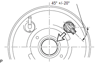 Text in Illustration
.png) |
Center of the Brake Booster Assembly |
(b) Connect the connector to the vacuum warning switch assembly.
Removal
REMOVAL
PROCEDURE
1. REMOVE VACUUM WARNING SWITCH ASSEMBLY
(a) Disconnect the connector from the vacuum warning switch assembly.
(b) Remove the vacuum warning switch assembly from the brake booster assembly.
2. REMOVE VACUUM WARNING SWITCH GROMMET
(a) Remove the vacuum warning switch grommet from the brake booster assembly.
 Vacuum Pump
Components
COMPONENTS
ILLUSTRATION
Installation
INSTALLATION
PROCEDURE
1. INSTALL VACUUM PUMP ASSEMBLY
(a) Apply engine oil to the 2 O-rings on the vacuum pump assembly.
(b) Apply engine ...

Other materials:
Engine Hood Courtesy Switch
Components
COMPONENTS
ILLUSTRATION
Inspection
INSPECTION
PROCEDURE
1. INSPECT HOOD COURTESY SWITCH (HOOD LOCK ASSEMBLY)
(a) Check the resistance.
(1) Measure the resistance according to the value(s) in the table below.
Text in Illustration
*a
...
Transmitter ID not Received in Main Mode (C2126/26)
DESCRIPTION
After all transmitter IDs are registered, DTC C2126/26 is stored in the tire
pressure warning ECU and receiver and the tire pressure warning light blinks for
1 minute and then illuminates.
When the tire pressure warning ECU and receiver successfully receives radio waves
from all ...
On-vehicle Inspection
ON-VEHICLE INSPECTION
PROCEDURE
1. INSPECT CAMSHAFT TIMING GEAR BOLT
(a) Remove the camshaft timing oil control solenoid assembly (See page
).
(b) Check that the plunger strokes when the plunger in the center of
the camshaft timing gear bolt is pressed.
Standard stroke:
4 ...
