Toyota Tacoma (2015-2018) Service Manual: Dtc Check / Clear
DTC CHECK / CLEAR
1. CHECK DTC (for TIRE PRESSURE WARNING ECU AND RECEIVER) (USING TECHSTREAM)
(a) Turn the ignition switch off.
(b) Connect the Techstream to the DLC3.
(c) Turn the ignition switch to ON.
(d) Turn the Techstream on.
(e) Enter the following menus: Chassis / Tire Pressure Monitor / Trouble Codes.
(f) Read the DTCs.
2. CHECK DTC (for TIRE PRESSURE WARNING ECU AND RECEIVER) (USING SST CHECK WIRE)
(a) Turn the ignition switch off.
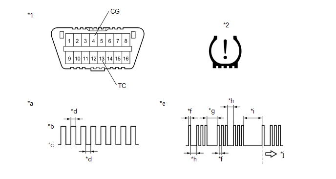 Text in Illustration
|
*1 |
DLC3 |
*2 |
Tire Pressure Warning Light |
|
*a |
Normal System Code |
*b |
ON |
|
*c |
OFF |
*d |
0.25 sec. |
|
*e |
Code 13 and 33 |
*f |
0.5 sec. |
|
*g |
2.5 sec. |
*h |
1.5 sec. |
|
*i |
4.5 sec. |
*j |
Repeat |
(b) Using SST, connect terminals 13 (TC) and 4 (CG) of the DLC3.
SST: 09843-18040
(c) Turn the ignition switch to ON.
(d) Read and record any DTCs indicated by the tire pressure warning light in the combination meter assembly. Refer to the illustration for examples of a normal system code and codes 13 and 33.
HINT:
- If the tire pressure warning light does not indicate any DTCs or the
normal system code, inspect the tire pressure warning light circuit or TC
and CG terminal circuit.
Trouble Area
Link
Tire pressure warning light circuit
.gif)
TC and CG terminal circuit
- If 2 or more malfunctions are indicated at the same time, the lowest numbered DTC is displayed first.
(e) Refer to Diagnostic Trouble Code Chart for DTC information (See page
).
(f) After completing the check, turn the ignition switch off and remove SST from the DLC3.
3. CHECK DTC (for MAIN BODY ECU (MULTIPLEX NETWORK BODY ECU))
(a) Turn the ignition switch off.
(b) Connect the Techstream to the DLC3.
(c) Turn the ignition switch to ON.
(d) Turn the Techstream on.
(e) Enter the following menus: Body Electrical / Main Body / Trouble Codes.
(f) Read the DTCs.
4. CLEAR DTC (for TIRE PRESSURE WARNING ECU AND RECEIVER)
HINT:
After repairing the malfunctions, clear the DTCs.
(a) Turn the ignition switch off.
(b) Connect the Techstream to the DLC3.
(c) Turn the ignition switch to ON.
(d) Turn the Techstream on.
(e) Enter the following menus: Chassis / Tire Pressure Monitor / Trouble Codes.
(f) Clear the DTCs following the prompts on the Techstream screen.
HINT:
Refer to the Techstream operator's manual for further details.
5. CLEAR DTC (for MAIN BODY ECU (MULTIPLEX NETWORK BODY ECU))
HINT:
After repairing the malfunctions, clear the DTCs.
(a) Turn the ignition switch off.
(b) Connect the Techstream to the DLC3.
(c) Turn the ignition switch to ON.
(d) Turn the Techstream on.
(e) Enter the following menus: Body Electrical / Main Body / Trouble Codes.
(f) Clear the DTCs following the prompts on the Techstream screen.
HINT:
Refer to the Techstream operator's manual for further details.
 Data List / Active Test
DATA LIST / ACTIVE TEST
1. READ DATA LIST
HINT:
Using the Techstream to read the Data List allows the values or states of switches,
sensors, actuators and other items to be read without removing ...
 Transmitter ID not Received in Main Mode (C2126/26)
DESCRIPTION
After all transmitter IDs are registered, DTC C2126/26 is stored in the tire
pressure warning ECU and receiver and the tire pressure warning light blinks for
1 minute and then illumin ...
Other materials:
Data List / Active Test
DATA LIST / ACTIVE TEST
HINT:
By accessing the Data List displayed by the Techstream, you can check values
of switches and sensors without removing any parts. Reading the Data List as the
first step of troubleshooting is one method to shorten diagnostic time.
1. DATA LIST FOR OCCUPANT DETECTI ...
Steering Angle Sensor Output Malfunction (C1434)
DESCRIPTION
Steering angle sensor signals are input to the skid control ECU (brake actuator
assembly) via the CAN communication system.
HINT:
When a malfunction occurs in the communication line to the steering angle sensor,
U0126 is output. If a DTC related to the CAN communication line is ou ...
Disassembly
DISASSEMBLY
PROCEDURE
1. REMOVE REAR BUMPER HOLE COVER
(a) Disengage the 2 clips to remove the rear bumper hole cover.
2. REMOVE REAR BUMPER PAD SUB-ASSEMBLY
(a) Separate the 2 license plate light assemblies as shown in the illustr ...
