Toyota Tacoma (2005–2015) Owners Manual: Theft deterrent system
Engine immobilizer system
The vehicle’s keys have built-in transponder chips that prevent the engine from starting if the key has not been previously registered in the vehicle’s on-board computer.
Never leave the keys inside the vehicle when you leave the vehicle.
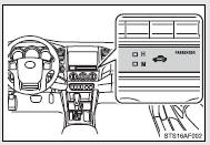
The indicator light flashes after the key has been removed from the engine switch to indicate that the system is operating.
The indicator light stops flashing after the registered key has been inserted into the engine switch to indicate that the system has been canceled.
■System maintenance
The vehicle has a maintenance-free type engine immobilizer system.
■Conditions that may cause the system to malfunction
●If the key is in contact with a metallic object
●If the key is in close proximity to or touching a key to the security system (key with a built-in transponder chip) of another vehicle
■Certifications for the engine immobilizer system
 For vehicles sold in U.S.A.
FCC ID: MOZRI-21BTY
This device complies with part 15 of the FCC Rules. Operation is subject to the following two conditions: (1) This device may not cause harmful interference, and (2) this device must accept any interference received, including interference that may cause undesired operation.
FCC WARNING: Changes or modifications not expressly approved by the party responsible for compliance could void the user’s authority to operate the equipment.
 For vehicles sold in Canada
This device complies with Industry Canada licence-exempt RSS standard( s). Operation is subject to the following two conditions: (1) this device may not cause interference, and (2) this device must accept any interference, including interference that may cause undesired operation of the device.
For vehicles sold in New Caledonia
“Hereby, Tokai Rika Co., Ltd., declares that this RI-21BTY is in compliance with the essential requirements and other relevant provisions of Directive 1999/5/EC.”
NOTICE
■To ensure the system operates correctly
Do not modify or remove the system. If modified or removed, the proper operation of the system cannot be guaranteed.
 Refueling
Opening the fuel tank cap
Perform the following steps to open the fuel tank cap.
■ Before refueling the vehicle
Turn the engine switch off and ensure that all the doors and windows are closed ...

Other materials:
Reassembly
REASSEMBLY
CAUTION / NOTICE / HINT
HINT:
Use the same procedure for both the LH and RH sides.
The procedure described below is for the LH side.
PROCEDURE
1. INSTALL FOG LIGHT BULB
(a) Turn the fog light bulb in the direction indicated by the arrow in
the illust ...
Brake
General Maintenance
GENERAL MAINTENANCE
PROCEDURE
1. INSPECT BRAKE LINE PIPES AND HOSES
HINT:
Work in a well-lighted area. Turn the front wheels fully to the right or left
before beginning.
(a) Check all the brake lines and hoses for:
Damage
Wear
Deformation
Cracks
...
Diagnostic Trouble Code Chart
DIAGNOSTIC TROUBLE CODE CHART
Rear View Monitor System
DTC Code
Detection Item
See page
C1622
Open or Short Circuit in Back Camera Signal
...
