Toyota Tacoma (2015-2018) Service Manual: Reassembly
REASSEMBLY
PROCEDURE
1. INSTALL FRONT BUMPER COVER INSERT LH
|
(a) Engage the clip to install the front bumper cover insert LH. |
|
(b) Install the bolt.
Torque:
5.9 N·m {60 kgf·cm, 52 in·lbf}
2. INSTALL FRONT BUMPER COVER INSERT RH
HINT:
Use the same procedure as for the LH side.
3. INSTALL NO. 2 FRONT BUMPER EXTENSION SUB-ASSEMBLY LH
|
(a) Install the No. 2 front bumper extension sub-assembly LH with the 3 nuts. Torque: 58 N·m {591 kgf·cm, 43 ft·lbf} |
|
.png)
4. INSTALL NO. 2 FRONT BUMPER EXTENSION SUB-ASSEMBLY RH
HINT:
Use the same procedure as for the LH side.
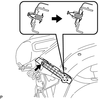
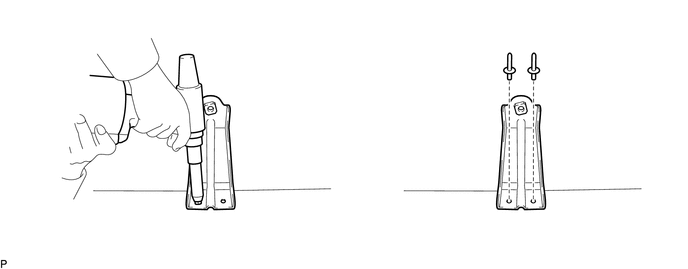
5. INSTALL LOWER FRONT BUMPER RETAINER
HINT:
Use the same procedure for both lower front bumper retainers.
(a) Install the lower front bumper retainer.
(b) Install a nose piece to an air riveter or hand riveter.
(c) Insert the mandrel part of a new rivet into the nose piece.
(d) Place the riveter upright against the lower front bumper retainer and install the 2 rivets.
HINT:
If the rivet cannot be cut, pull it once and cut it.
NOTICE:
- Do not pry the rivet with the riveter as this will cause damage to the
riveter and mandrel.
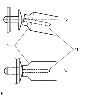
*1
Mandrel
*a
Riveter
*b
Incorrect
*c
Correct
- Confirm that the rivets are seated properly against the lower front
bumper retainer.
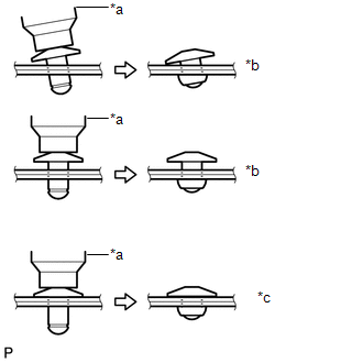
*a
Riveter
*b
Incorrect
*c
Correct
- Do not tilt the riveter when installing the rivet to the lower front bumper retainer.
- Do not leave any space between the rivet head and lower front bumper retainer.
- Do not leave any space between the lower front bumper retainer and front
bumper reinforcement. Firmly hold together the 2 items while installing
the rivet.
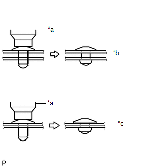
*a
Riveter
*b
Incorrect
*c
Correct
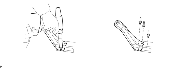
6. INSTALL FRONT BUMPER INNER ARM SUB-ASSEMBLY LH
(a) Install the front bumper inner arm sub-assembly LH.
(b) Install a nose piece to an air riveter or hand riveter.
(c) Insert the mandrel part of a new rivet into the nose piece.
(d) Place the riveter upright against the front bumper inner arm sub-assembly LH and install the 3 rivets.
HINT:
If the rivet cannot be cut, pull it once and cut it.
NOTICE:
- Do not pry the rivet with the riveter as this will cause damage to the
riveter and mandrel.
*1
Mandrel
*a
Riveter
*b
Incorrect
*c
Correct
- Confirm that the rivets are seated properly against the front bumper
inner arm sub-assembly LH.
*a
Riveter
*b
Incorrect
*c
Correct
- Do not tilt the riveter when installing the rivet to the front bumper inner arm sub-assembly LH.
- Do not leave any space between the rivet head and front bumper inner arm sub-assembly LH.
- Do not leave any space between the front bumper inner arm sub-assembly
LH and front bumper reinforcement. Firmly hold together the 2 items while
installing the rivet.
*a
Riveter
*b
Incorrect
*c
Correct
7. INSTALL FRONT BUMPER INNER ARM SUB-ASSEMBLY RH
HINT:
Use the same procedure as for the LH side.
8. INSTALL FRONT BUMPER REINFORCEMENT
|
(a) Install the front bumper reinforcement with the 6 nuts. Torque: 58 N·m {591 kgf·cm, 43 ft·lbf} |
|
.png)
9. INSTALL FRONT BUMPER ENERGY ABSORBER
|
(a) Engage the guide and 9 claws to install the front bumper energy absorber. |
|
.png)
10. INSTALL HEADLIGHT MOUNTING BRACKET
|
(a) Engage the 2 claws to install the headlight mounting bracket. HINT: Use the same procedure for the RH side and LH side. |
|
.png)
11. INSTALL FRONT BUMPER ARM MOUNTING BRACKET LH
|
(a) Engage the claw and install the front bumper arm mounting bracket LH with the 2 bolts. Torque: 4.0 N·m {41 kgf·cm, 35 in·lbf} |
|
.png)
12. INSTALL FRONT BUMPER ARM MOUNTING BRACKET RH
HINT:
Use the same procedure as for the LH side.
13. INSTALL RADIATOR SIDE DEFLECTOR LH
|
(a) Engage the 3 claws to install the radiator side deflector LH. |
|
.png)
(b) Install the clips.
14. INSTALL RADIATOR SIDE DEFLECTOR RH
HINT:
Use the same procedure as for the LH side.
15. INSTALL FRONT BUMPER UPPER CENTER RETAINER
|
(a) Install the front bumper upper center retainer with the 6 nuts. Torque: 5.5 N·m {56 kgf·cm, 49 in·lbf} |
|
.png)
(b) Engage the 2 clamps to install the wire harness.
16. INSTALL FRONT FENDER LINER RETAINER
|
(a) Engage the claw to install the front fender liner retainer. |
|
.png)
17. INSTALL FRONT VALANCE PANEL
|
(a) Engage the 14 claws to install the front valance panel. |
|
.png)
(b) Install the 2 outside moulding retainers.
18. INSTALL LOWER NO. 1 RADIATOR GRILLE
|
(a) Engage the 23 claws to install the lower No. 1 radiator grille. |
|
.png)
19. INSTALL FRONT BUMPER HOLE COVER LH (w/o Fog Light)
|
(a) Engage the 6 claws to install the front bumper hole cover LH. |
|
.png)
20. INSTALL FRONT BUMPER HOLE COVER RH (w/o Fog Light)
HINT:
Use the same procedure as for the LH side.
21. INSTALL FOG LIGHT COVER LH (w/ Fog Light)
|
(a) for Halogen Fog Light: (1) Engage the 6 claws to install the fog light cover LH. |
|
.png)
|
(b) for LED Fog Light: (1) Engage the 6 claws to install the fog light cover LH. |
|
.png)
22. INSTALL FOG LIGHT COVER RH (w/ Fog Light)
HINT:
Use the same procedure as for the LH side.
23. INSTALL FOG LIGHT ASSEMBLY LH (w/ Fog Light)
|
(a) for Halogen Fog Light: (1) Engage the 2 guides to install the fog light assembly LH. (2) Install the screw. |
|
.png)
|
(b) for LED Fog Light: (1) Engage the 2 guides to install the fog light assembly LH. (2) Install the screw. |
|
.png)
24. INSTALL FOG LIGHT ASSEMBLY RH (w/ Fog Light)
HINT:
Use the same procedure as for the LH side.
25. INSTALL NO. 4 ENGINE ROOM WIRE (w/ Fog Light)
|
(a) Engage the 8 clamps to install the No. 4 engine room wire. |
|
.png)
(b) Connect the 2 connectors.
26. INSTALL FRONT LICENSE PLATE BRACKET
|
(a) Install the front license plate bracket with the 2 screws. |
|
.png)
 Disassembly
DISASSEMBLY
PROCEDURE
1. REMOVE FRONT LICENSE PLATE BRACKET
(a) Remove the 2 screws and front license plate bracket.
2. REMOVE NO. 4 ENGINE ROO ...
 Removal
REMOVAL
PROCEDURE
1. REMOVE FRONT FENDER MUDGUARD (w/ Mudguard)
Click here
2. REMOVE FRONT FENDER WHEEL OPENING MOULDING (w/ Over Fender)
Click here
3. REMOVE FRONT NO. 1 WHEEL OPENING EXTEN ...
Other materials:
Problem Symptoms Table
PROBLEM SYMPTOMS TABLE
HINT:
Use the table below to help determine the cause of problem symptoms.
If multiple suspected areas are listed, the potential causes of the symptoms
are listed in order of probability in the "Suspected Area" column of the
table. Check each sy ...
Short in Driver Side Knee Airbag Squib Circuit (B1860/64-B1863/64)
DESCRIPTION
The driver side knee airbag squib circuit consists of the airbag sensor assembly
and lower No. 1 instrument panel airbag assembly.
The airbag sensor assembly uses this circuit to deploy the airbag when deployment
conditions are met.
These DTCs are stored when a malfunction is dete ...
Dtc Check / Clear
DTC CHECK / CLEAR
1. CHECK DTC (for TIRE PRESSURE WARNING ECU AND RECEIVER) (USING TECHSTREAM)
(a) Turn the ignition switch off.
(b) Connect the Techstream to the DLC3.
(c) Turn the ignition switch to ON.
(d) Turn the Techstream on.
(e) Enter the following menus: Chassis / Tire Pressure Monito ...
