Toyota Tacoma (2015-2018) Service Manual: Inspection
INSPECTION
PROCEDURE
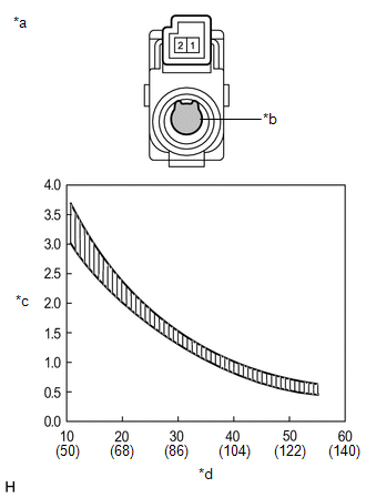
1. INSPECT COOLER (ROOM TEMPERATURE. SENSOR) THERMISTOR
(a) Check the resistance.
|
(1) Measure the resistance according to the value(s) in the table below. Text in Illustration
Standard Resistance:
NOTICE:
If the result is not as specified, replace the cooler thermistor (room temperature sensor). |
|
 Components
COMPONENTS
ILLUSTRATION
...
 Removal
REMOVAL
PROCEDURE
1. REMOVE FRONT DOOR SCUFF PLATE LH (for Double Cab)
2. REMOVE FRONT DOOR SCUFF PLATE LH (for Access Cab)
3. REMOVE COWL SIDE TRIM BOARD LH
4. REMOVE CENTER INSTRUME ...
Other materials:
Steering Angle Sensor (C1A47)
DESCRIPTION
The forward recognition camera receives steering angle information from the spiral
cable with sensor sub-assembly. If the forward recognition camera detects a spiral
cable with sensor sub-assembly, DTC C1A47 is stored.
DTC No.
Detection Item
DTC Det ...
Trailer towing
Your vehicle is designed primarily as a passenger-and-load-carrying vehicle.
Towing a trailer can have an adverse impact on handling, performance, braking, durability,
and fuel consumption. For your safety and the safety of others, you must not overload
your vehicle or trailer. You must also e ...
Installation
INSTALLATION
CAUTION / NOTICE / HINT
NOTICE:
Always use a new grommet and valve core when installing the tire pressure
warning valve and transmitter.
Check that the washer and nut are not damaged, and replace them if necessary.
If installing a new tire pressure warning valv ...
