Toyota Tacoma (2015-2018) Service Manual: Terminals Of Ecu
TERMINALS OF ECU
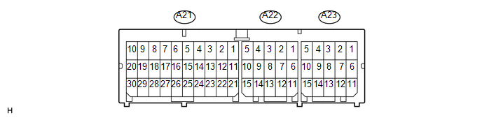
1. AIRBAG SENSOR ASSEMBLY
|
Terminal No. |
Terminal Symbol |
Destination |
|---|---|---|
|
A21-1 |
P2+ |
Instrument panel passenger without door airbag assembly (Front passenger side squib 2nd step) |
|
A21-2 |
P2- |
Instrument panel passenger without door airbag assembly (Front passenger side squib 2nd step) |
|
A21-3 |
P- |
Instrument panel passenger without door airbag assembly (Front passenger side squib) |
|
A21-4 |
P+ |
Instrument panel passenger without door airbag assembly (Front passenger side squib) |
|
A21-5 |
D+ |
Horn button assembly (Driver side squib) |
|
A21-6 |
D- |
Horn button assembly (Driver side squib) |
|
A21-7 |
D2- |
Horn button assembly (Driver side squib 2nd step) |
|
A21-8 |
D2+ |
Horn button assembly (Driver side squib 2nd step) |
|
A21-9 |
DK+ |
Lower No. 1 instrument panel airbag assembly (Driver side knee airbag squib) |
|
A21-10 |
DK- |
Lower No. 1 instrument panel airbag assembly (Driver side knee airbag squib) |
|
A21-11 |
VHP+ |
Instrument panel passenger without door airbag assembly (Variable vent hole squib) |
|
A21-12 |
VHP- |
Instrument panel passenger without door airbag assembly (Variable vent hole squib) |
|
A21-13 |
CANH |
CAN |
|
A21-17 |
P-AB |
Air conditioning control assembly (Passenger airbag ON/OFF indicator) |
|
A21-19 |
PK+ |
Lower No. 2 instrument panel airbag assembly (Passenger side knee airbag squib) |
|
A21-20 |
PK- |
Lower No. 2 instrument panel airbag assembly (Passenger side knee airbag squib) |
|
A21-21 |
IG2 |
IGN fuse (Power Source) |
|
A21-22 |
CANL |
CAN |
|
A21-23 |
PAON |
Air conditioning control assembly (Passenger airbag ON/OFF indicator) |
|
A21-25 |
E1 |
Ground |
|
A21-26 |
E2 |
Ground |
|
A21-27 |
-SR |
Front airbag sensor RH |
|
A21-28 |
-SL |
Front airbag sensor LH |
|
A21-29 |
+SR |
Front airbag sensor RH |
|
A21-30 |
+SL |
Front airbag sensor LH |
|
A22-1 |
PL- |
Front seat outer belt assembly LH (Front pretensioner squib LH) |
|
A22-2 |
PL+ |
Front seat outer belt assembly RH (Front pretensioner squib RH) |
|
A22-6 |
ICL- |
Curtain shield airbag assembly LH (Driver side curtain shield squib) |
|
A22-7 |
ICL+ |
Curtain shield airbag assembly LH (Driver side curtain shield squib) |
|
A22-8 |
BBL+ |
Side airbag sensor assembly LH |
|
A22-9 |
SFL+ |
Front seat airbag assembly LH (Side squib LH) |
|
A22-10 |
SFL- |
Front seat airbag assembly LH (Side squib LH) |
|
A22-11 |
LBE+ |
Front seat inner belt assembly LH |
|
A22-12 |
LBE- |
Front seat inner belt assembly LH |
|
A22-13 |
LSP- |
Seat position airbag sensor |
|
A22-14 |
LSP+ |
Seat position airbag sensor |
|
A22-15 |
BBL- |
Side airbag sensor assembly LH |
|
A23-4 |
PR+ |
Front seat outer belt assembly RH (Front pretensioner squib RH) |
|
A23-5 |
PR- |
Front seat outer belt assembly RH (Front pretensioner squib RH) |
|
A23-6 |
SFR- |
Front seat airbag assembly RH (Side squib RH) |
|
A23-7 |
SFR+ |
Front seat airbag assembly RH (Side squib RH) |
|
A23-8 |
BBR+ |
Side airbag sensor assembly RH |
|
A23-9 |
ICR+ |
Curtain shield airbag assembly RH (Front Passenger side curtain shield squib) |
|
A23-10 |
ICR- |
Curtain shield airbag assembly RH (Front Passenger side curtain shield squib) |
|
A23-11 |
BBR- |
Side airbag sensor assembly RH |
|
A23-12 |
FSR+ |
Occupant detection ECU |
|
A23-13 |
FSR- |
Occupant detection ECU |
 Dtc Check / Clear
DTC CHECK / CLEAR
1. SUPPLEMENTAL RESTRAINT SYSTEM DTC CHECK (USING SST CHECK WIRE)
(a) Check the DTCs (Present DTCs).
(1) Turn the ignition switch to ON, and wait for approximately 60 seconds.
...
 Data List / Active Test
DATA LIST / ACTIVE TEST
HINT:
By accessing the Data List displayed on the Techstream, you can perform such
functions as reading the values of switches and sensors without removing any parts.
Rea ...
Other materials:
Inspection
INSPECTION
PROCEDURE
1. INSPECT BRAKE BOOSTER PUMP ASSEMBLY
(a) Connect the positive (+) lead from the battery to the red cable of the pump,
and the negative (-) lead to the black cable.
(b) Check the brake booster pump operation.
OK:
Operation sound is heard. ...
Steering Pad Switch
Components
COMPONENTS
ILLUSTRATION
*1
STEERING PAD SWITCH ASSEMBLY
-
-
Removal
REMOVAL
PROCEDURE
1. REMOVE STEERING PAD
(See page )
2. REMOVE STEERING PAD SWITCH ASSEMBLY
(a) Disconnect the 2 connectors.
...
Inspection
INSPECTION
PROCEDURE
1. INSPECT CENTER STOP LIGHT ASSEMBLY (for LED Type Stop Light)
(a) Check the illuminates.
(1) Apply battery voltage to the connector and check the light illumination
condition.
Text in Illustration
*a
Component without ...
