Toyota Tacoma (2015-2018) Service Manual: Dtc Check / Clear
DTC CHECK / CLEAR
1. SUPPLEMENTAL RESTRAINT SYSTEM DTC CHECK (USING SST CHECK WIRE)
(a) Check the DTCs (Present DTCs).
(1) Turn the ignition switch to ON, and wait for approximately 60 seconds.
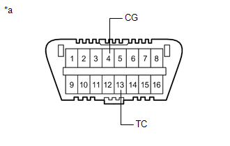
(2) Using SST, connect terminals TC and CG of the DLC3.
SST: 09843-18040
NOTICE:
Connect the terminals to the correct positions to avoid a malfunction.
(b) Check the DTCs (Past DTCs).
(1) Using SST, connect terminals TC and CG of the DLC3.
SST: 09843-18040
NOTICE:
Connect the terminals to the correct positions to avoid a malfunction.
(2) Turn the ignition switch to ON, and wait for approximately 60 seconds.
Text in Illustration|
*a |
DLC3 |
(c) Read the DTCs.
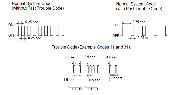
(1) Observe the SRS warning light blinking patterns to read DTCs. As examples, the blinking patterns for the normal system indication, the past DTC indication, and the present DTC indication are shown in the illustration.
- Normal system indication
The SRS warning light blinks twice per second.
- Past DTC indication
When any past DTCs are stored in the airbag sensor assembly, the SRS warning light blinks only once per second.
- Present DTC indication
The first blinking indicates the first digit of a 2-digit DTC. The second blinking occurs after a 1.5-second pause to indicate the second digit.
If there are 2 or more DTCs, there is a 2.5-second pause after each one. After all the DTC are displayed, there is a 4.0-second pause, and they are repeated.
HINT:
- If 2 or more malfunctions are found, the indication begins with the smaller numbered code.
- If DTCs are indicated without connecting the terminals, proceed to "TC
and CG Terminal Circuit" (See page
.gif) ).
).
2. DTC CLEAR (USING SST CHECK WIRE)
(a) Clear the DTCs.
(1) When the ignition switch is turned off (turned to the lock position), the DTCs are cleared.
HINT:
Depending on the DTCs, the DTCs may not be cleared by turning off the ignition switch. In this case, proceed to the next procedure.
(2) Using SST, connect terminals TC and CG of the DLC3, and then turn the ignition switch to ON.
SST: 09843-18040
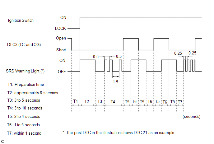
(3) Disconnect terminal TC of the DLC3 within 3 to 10 seconds after the DTCs being output, and check if the SRS warning light comes on within 3 seconds.
(4) Within 2 to 4 seconds of the SRS warning light coming on, connect terminals TC and CG of the DLC3.
(5) The SRS warning light should turn off within 2 to 4 seconds after connecting terminals TC and CG of the DLC3. Then, disconnect terminal TC within 2 to 4 seconds after the SRS warning light turning off.
(6) The SRS warning light comes on again within 2 to 4 seconds after disconnecting terminal TC. Then, reconnect terminals TC and CG within 2 to 4 seconds after the SRS warning light coming on, connect terminals TC and CG of the DLC3.
(7) Check if the SRS warning light turns off 2 to 4 seconds after connecting terminals TC and CG of the DLC3. Also check if the normal system indication is displayed within 1 second of the SRS warning light turning off.
If DTCs are not cleared, repeat this procedure until the codes are cleared.
3. SUPPLEMENTAL RESTRAINT SYSTEM DTC CHECK (USING TECHSTREAM)
(a) Check the DTCs.
(1) Connect the Techstream to the DLC3.
(2) Turn the ignition switch to ON and turn the Techstream on.
(3) Check the DTCs by following the prompts on the Techstream screen.
HINT:
Refer to the Techstream operator manual for further details.
(b) Clear the DTCs.
(1) Connect the Techstream to the DLC3.
(2) Turn the ignition switch to ON and turn the Techstream on.
(3) Clear the DTCs by following the prompts on the Techstream screen.
HINT:
Refer to the Techstream operator's manual for further details.
 Diagnosis System
DIAGNOSIS SYSTEM
1. CHECK DLC3
(a) The vehicle ECUs use ISO 15765-4 communication protocol. The terminal arrangement
of the DLC3 complies with ISO 15031-3 and matches the ISO 15765-4 format.
...
 Terminals Of Ecu
TERMINALS OF ECU
1. AIRBAG SENSOR ASSEMBLY
Terminal No.
Terminal Symbol
Destination
A21-1
P2+
Instrument panel passenger wit ...
Other materials:
Diagnostic Trouble Code Chart
DIAGNOSTIC TROUBLE CODE CHART
Rear View Monitor System
DTC Code
Detection Item
See page
C1622
Open or Short Circuit in Back Camera Signal
...
Disassembly
DISASSEMBLY
PROCEDURE
1. REMOVE REAR AXLE SHAFT SNAP RING
(a) Using a snap ring expander, remove the snap ring.
2. REMOVE REAR AXLE SHAFT
(a) Using SST and press, remove the rear axle shaft.
SST: 09521-25011
SST: 09521-25021
3. REMOVE REAR AXLE BEARING RETAINER INNER
(a) Remove the rear ...
Four-wheel drive system
Use the front-wheel drive control switch to select the following transfer modes.
H2 (high speed position, two-wheel
drive)
Use this for normal driving on dry hard-surfaced roads.
This position gives greater economy, quietest ride and least wear.
H4 (high speed position, four-wheel
drive) ...
