Toyota Tacoma (2015-2018) Service Manual: Inspection
INSPECTION
PROCEDURE
1. INSPECT BRAKE BOOSTER PUMP ASSEMBLY
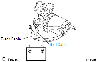
(a) Connect the positive (+) lead from the battery to the red cable of the pump, and the negative (-) lead to the black cable.
(b) Check the brake booster pump operation.
OK:
Operation sound is heard.
 Removal
REMOVAL
CAUTION / NOTICE / HINT
NOTICE:
Before starting the work, make sure that the ignition switch is off
and depress the brake pedal more than 20 times.
As high pressure is appli ...
 Reassembly
REASSEMBLY
PROCEDURE
1. INSTALL BRAKE BOOSTER ACCUMULATOR ASSEMBLY
(a) Place the brake booster pump in a vise with a cloth.
(b) Install the brake booster accumulator pipe, compression spring and ...
Other materials:
Air Mix Damper Control Servo Motor Circuit (Passenger Side) (B1441/41)
DESCRIPTION
This No. 2 air conditioning radiator damper servo sub-assembly (for front passenger
side air mix) is controlled by the air conditioning amplifier assembly and moves
the air mix damper (for front passenger side) to the desired position.
DTC No.
DTC Detection Co ...
Check Bus 5 Line for Short to GND
DESCRIPTION
There may be a short circuit between one of the CAN bus lines and GND when there
is no resistance between terminal 15 (CA5H) of the central gateway ECU (network
gateway ECU) and terminal 4 (CG) of the DLC3, or terminal 16 (CA5L) of the central
gateway ECU (network gateway ECU) and ...
Disassembly
DISASSEMBLY
CAUTION / NOTICE / HINT
HINT:
Use the same procedures for both the LH and RH sides.
The procedure described below is for the LH side.
PROCEDURE
1. REMOVE OUTER MIRROR
(a) Push the lower part of the mirror surface and tilt it.
Text in Illustration
...
