Toyota Tacoma (2015-2018) Service Manual: Terminals Of Ecu
TERMINALS OF ECU
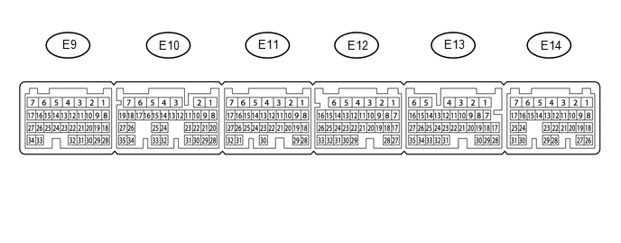
1. ECM
|
Terminal No. (Symbol) |
Wiring Color |
Terminal Description |
Condition |
Specified Condition |
|---|---|---|---|---|
|
E14-20 (TC) - E11-1 (E1) |
G - W-B |
DTC output signal |
Ignition switch ON |
11 to 14 V |
|
E14-20 (TC) - E11-1 (E1) |
G - W-B |
DTC output signal |
Ignition switch ON Connect terminals TC and CG of DLC3 |
Below 2 V |
|
E13-15 (ST1-) - E11-1 (E1) |
V - W-B |
Cruise cancel input signal |
Ignition switch ON Depress Brake pedal |
Below 1 V |
|
E13-15 (ST1-) - E11-1 (E1) |
V - W-B |
Cruise cancel input signal |
Ignition switch ON Release brake pedal |
11 to 14 V |
|
E13-16 (STP) - E11-1 (E1) |
P - W-B |
Stop light switch input signal |
Depress brake pedal |
11 to 14 V |
|
E13-16 (STP) - E11-1 (E1) |
P - W-B |
Stop light switch input signal |
Release brake pedal |
Below 1 V |
|
E13-17 (CCS) - E11-1 (E1) |
B - W-B |
Cruise control main switch output signal |
Ignition switch ON |
11 to 14 V |
|
E13-17 (CCS) - E11-1 (E1) |
B - W-B |
Cruise control main switch output signal |
Ignition switch ON CANCEL switch ON |
6.6 to 10.1 V |
|
E13-17 (CCS) - E11-1 (E1) |
B - W-B |
Cruise control main switch output signal |
Ignition switch ON -(COAST)/SET switch ON |
4.5 to 7.1 V |
|
E13-17 (CCS) - E11-1 (E1) |
B - W-B |
Cruise control main switch output signal |
Ignition switch ON +(ACCEL)/RES switch ON |
2.3 to 4 V |
|
E13-17 (CCS) - E11-1 (E1) |
B - W-B |
Cruise control main switch output signal |
Ignition switch ON MAIN switch ON |
Below 1 V |
|
E11-1 (E1) - Body ground |
W-B - Body ground |
Ground |
Always |
Below 1 V |
|
E12-27 (D) - E11-1 (E1)*1 |
R - W-B |
Park/neutral position switch signal |
Ignition switch ON, shift lever D or 3 positions |
11 to 14 V |
|
E12-27 (D) - E11-1 (E1)*1 |
R - W-B |
Park/neutral position switch signal |
Ignition switch ON, shift lever other than D and 3 positions |
Below 1 V |
|
E12-27 (D) - E11-1 (E1)*2 |
R - W-B |
Clutch switch input signal |
Ignition switch ON Depress clutch pedal |
Below 1 V |
|
E12-27 (D) - E11-1 (E1)*2 |
R - W-B |
Clutch switch input signal |
Ignition switch ON Release clutch pedal |
11 to 14 V |
- *1: for Automatic Transmission
- *2: for Manual Transmission
 Diagnosis System
DIAGNOSIS SYSTEM
1. DESCRIPTION
The ECM stores DTCs (Diagnostic Trouble Codes) when trouble occurs on the vehicle.
The diagnosis system allows reading of DTCs stored in the ECM when a the Techstre ...
 Data List / Active Test
DATA LIST / ACTIVE TEST
1. DATA LIST
HINT:
Using the Techstream to read the Data List allows the values or states of switches,
sensors, actuators and other items to be read without removing any p ...
Other materials:
Front Camera Module Circuit (C1AA0)
DESCRIPTION
When an internal malfunction is detected in the forward recognition camera, DTC
C1AA0 is stored.
DTC No.
Detection Item
DTC Detection Condition
Trouble Area
C1AA0
Front Camera Module Circuit
3 seconds ...
System Voltage Circuit Short to Ground or Open (P056014)
DESCRIPTION
The battery supplies power to the ECM even when the ignition switch is off. This
power allows the ECM to store data such as DTC history, freeze frame data and fuel
trim values. If the battery voltage falls below a minimum level, the ECM data is
cleared and the ECM determines that ...
Radio Antenna
Components
COMPONENTS
ILLUSTRATION
Removal
REMOVAL
PROCEDURE
1. REMOVE ROOF HEADLINING ASSEMBLY (for Double Cab)
(See page )
2. REMOVE ROOF HEADLINING ASSEMBLY (for Access Cab)
(See page )
3. REMOVE ANTENNA ASSEMBLY WITH HOLDER
(a) Disengage the 3 clamps.
(b) Remove the nut.
...
