Toyota Tacoma (2015-2018) Service Manual: Torque Converter Clutch Circuit Short to Ground (P074011)
DESCRIPTION
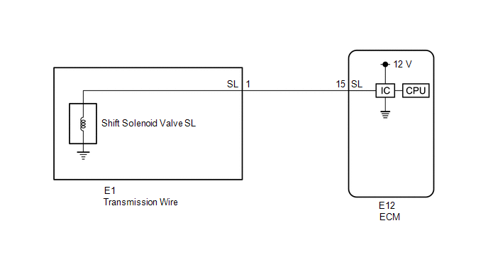
Shift solenoid valve SL is turned on and off by signals from the ECM to control the hydraulic pressure acting on the lock-up relay valve, which then controls operation of the lock-up clutch.
|
DTC No. |
DTC Detection Condition |
Trouble Area |
SAE |
|---|---|---|---|
|
P074011 |
The shift solenoid valve SL terminal voltage level is low, when the shift solenoid valve SL is operated (2 trip detection logic). |
|
P2769 |
Fail-safe function:
If the ECM detects a malfunction, it turns shift solenoid valve SL off.
MONITOR DESCRIPTION
Based on the signals from the throttle position sensor, the air flow meter and the crankshaft position sensor, the ECM sends a signal to shift solenoid valve SL to regulate the hydraulic pressure and provide smoother torque converter engagement. Shift solenoid valve SL responds to commands from the ECM. The valve controls the lock-up relay valve to perform the torque-converter lock-up function. If the ECM detects a in the shift solenoid valve SL circuit, it will illuminate the MIL and store the DTC.
MONITOR STRATEGY
|
Related DTCs |
P2769: Shift solenoid valve SL/Range check |
|
Required sensors/Components |
Shift solenoid valve SL |
|
Frequency of operation |
Continuous |
|
Duration |
1 time |
|
MIL operation |
2 driving cycles |
|
Sequence of operation |
None |
TYPICAL ENABLING CONDITIONS
All:|
The monitor will run whenever the following DTCs are not stored |
None |
|
Battery voltage |
8 V or higher |
|
Ignition switch |
ON |
|
Starter |
OFF |
|
Command to shift solenoid valve SL |
ON |
|
Time after command to solenoid OFF to ON |
More than 0.008192 sec. |
TYPICAL MALFUNCTION THRESHOLDS
|
Solenoid terminal voltage level |
Low |
COMPONENT OPERATING RANGE
|
Solenoid terminal voltage level |
High |
CONFIRMATION DRIVING PATTERN
CAUTION:
When performing the confirmation driving pattern, obey all speed limits and traffic laws.
HINT:
- After repairs have been completed, clear the DTCs and then check that the vehicle has returned to normal by performing the following All Readiness check procedure.
- When clearing the permanent DTCs, refer to the Clear Permanent DTC procedure
(See page
.gif) ).
).
- Connect the Techstream to the DLC3.
- Turn the ignition switch to ON and turn the Techstream on.
- Clear the DTCs (even if no DTCs are stored, perform the clear DTC procedure).
- Turn the ignition switch off and wait for 2 minutes or more.
- Turn the ignition switch to ON and turn the Techstream on.
- Start the engine.
- Perform the Lock-up Function inspection in Road Test (See page
). [*1]
HINT:
[*1] : Normal judgment procedure.
The normal judgment procedure is used to complete DTC judgment and also used when clearing permanent DTCs.
- Stop the vehicle.
- Enter the following menus: Powertrain / Transmission / Utility / All Readiness.
- Input the DTC: P074011.
- Check the DTC judgment result.
Techstream Display
Description
NORMAL
- DTC judgment completed
- System normal
ABNORMAL
- DTC judgment completed
- System abnormal
INCOMPLETE
- DTC judgment not completed
- Perform driving pattern after confirming DTC enabling conditions
N/A
- Unable to perform DTC judgment
- Number of DTCs which do not fulfill DTC preconditions has reached ECU memory limit
HINT:
- If the judgment result shows NORMAL, the system is normal.
- If the judgment result shows ABNORMAL, the system has a malfunction.
- If the judgment result shows INCOMPLETE or N/A, perform the normal judgment procedure again.
WIRING DIAGRAM
CAUTION / NOTICE / HINT
NOTICE:
- Perform the universal trip to clear permanent DTCs (See page
).
- Perform registration and/or initialization when parts related to the
automatic transmission are replaced (See page
).
PROCEDURE
|
1. |
INSPECT TRANSMISSION WIRE (SHIFT SOLENOID VALVE SL) |
|
(a) Disconnect the E1 transmission wire connector. |
|
(b) Measure the resistance according to the value(s) in the table below.
Standard Resistance:
|
Tester Connection |
Condition |
Specified Condition |
|---|---|---|
|
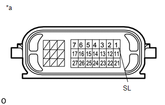
1 (SL) - Body ground |
20°C (68°F) |
11 to 15 Ω |
|
*a |
Component without harness connected (Transmission Wire) |
| NG | .gif) |
GO TO STEP 3 |
|
.gif)
|
2. |
CHECK HARNESS AND CONNECTOR (TRANSMISSION WIRE - ECM) |
|
(a) Disconnect the ECM connector. |
|
(b) Measure the resistance according to the value(s) in the table below.
Standard Resistance:
|
Tester Connection |
Condition |
Specified Condition |
|---|---|---|
|
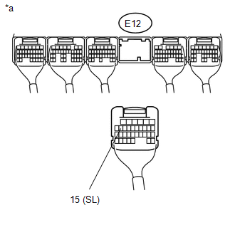
E12-15 (SL) - Body ground |
20°C (68°F) |
11 to 15 Ω |
|
*a |
Rear view of wire harness connector (to ECM) |
| OK | |
REPLACE ECM |
| NG | |
REPAIR OR REPLACE HARNESS OR CONNECTOR |
|
3. |
INSPECT SHIFT SOLENOID VALVE SL |
|
(a) Remove shift solenoid valve SL (See page
|
|
(b) Measure the resistance according to the value(s) in the table below.
Standard Resistance:
|
Tester Connection |
Condition |
Specified Condition |
|---|---|---|
|
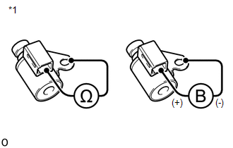
Shift solenoid valve SL connector terminal - Shift solenoid valve SL body |
20°C (68°F) |
11 to 15 Ω |
(c) Apply 12 V battery voltage to the shift solenoid valve and check that the valve moves and makes an operating noise.
OK:
|
Measurement Condition |
Specified Condition |
|---|---|
|
Valve moves and makes an operating noise |
|
*1 |
Shift Solenoid Valve SL |
| OK | |
REPLACE TRANSMISSION WIRE |
| NG | |
REPLACE SHIFT SOLENOID VALVE SL |
 Transmission Fluid Temperature Sensor "A" Circuit Short To Ground (P071011)
DESCRIPTION
The No. 1 ATF temperature sensor converts the fluid temperature into a resistance
value for use by the ECM.
The ECM applies a voltage to the temperature sensor through terminal THO1 of ...
 Torque Converter Clutch Circuit Short to Battery or Open (P074015)
DESCRIPTION
Shift solenoid valve SL is turned on and off by signals from the ECM to control
the hydraulic pressure acting on the lock-up relay valve, which then controls operation
of the lock-up ...
Other materials:
Problem Symptoms Table
PROBLEM SYMPTOMS TABLE
HINT:
Use the table below to help determine the cause of problem symptoms. If multiple
suspected areas are listed, the potential causes of the symptoms are listed in order
of probability in the "Suspected Area" column of the table. Check each symptom by
check ...
Freeze Frame Data
FREEZE FRAME DATA
DESCRIPTION
(a) When a pre-collision system DTC is stored, the millimeter wave radar sensor
assembly stores the current vehicle (ECU or sensor) state as Freeze Frame Data.
CHECK FREEZE FRAME DATA
(a) Connect the Techstream to the DLC3.
(b) Turn the ignition switch to ON.
(c ...
Removal
REMOVAL
PROCEDURE
1. REMOVE FRONT WHEEL
2. REMOVE REAR WHEEL
3. REMOVE TIRE PRESSURE WARNING VALVE AND TRANSMITTER
(a) Remove the cap and valve core to release the air from the tire.
NOTICE:
Keep the removed cap and valve core.
(b) After ensuring that a sufficient amount of air has been rele ...
