Toyota Tacoma (2015-2018) Service Manual: Diagnosis System
DIAGNOSIS SYSTEM
1. DESCRIPTION
The ECM stores DTCs (Diagnostic Trouble Codes) when trouble occurs on the vehicle. The diagnosis system allows reading of DTCs stored in the ECM when a the Techstream is connected to the DLC3 (Data Link Connector 3). If the CRUISE MAIN indicator light does not come on after a DTC check, it means that a malfunction has occurred in the cruise control system. Use a the Techstream or SST to check for DTCs.
2. CHECK DLC3
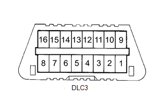
(a) The ECM uses ISO 9141-2 for data communication. The terminal arrangement of the DLC3 complies with SAE J1962 and matches the ISO 9141-2 format.
|
Terminal No. |
Tester Connection |
Condition |
Specification |
|---|---|---|---|
|
4 |
Chassis ground - Body Ground |
Always |
Below 1 Ω |
|
16 |
Battery positive - Body Ground |
Always |
9 to 14 V |
HINT:
If the Techstream display shows "UNABLE TO CONNECT TO VEHICLE" after connecting the Techstream to the DLC3 and turning the ignition to the ON position, there is a problem in either the vehicle or the Techstream itself.
- If communication is normal when connecting the tester to another vehicle, inspect the DLC3 on the original vehicle.
- If communication is still not possible when connecting the tester to another vehicle, it suggests the problem exists in the tester. In this case, consult the Service Department listed in the tester's instruction manual.
3. CHECK INDICATOR
(a) Turn the ignition switch to the ON position.
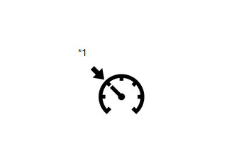 Text in Illustration
|
*1 |
Cruise Control Indicator Light |
(b) Check that the CRUISE MAIN indicator light comes on when the cruise control main switch ON-OFF button is pushed on, and that the indicator light goes off when the ON-OFF button is pushed off.
HINT:
If there is a problem with the ON/OFF illumination of the indicator light, inspect
the cruise main indicator light circuit (See page
.gif) ).
).
HINT:
If a malfunction occurs in the vehicle speed sensor, stop light switch assembly or other related parts while cruise control driving, the ECM actuates AUTO CANCEL of the cruise control. Then the power indicator turn off, the warning light illuminates and the vehicle display indicates a malfunction, to inform the driver of the malfunction. At the same time, data of the malfunction is stored as a diagnostic trouble code (DTC).
 Road Test
ROAD TEST
HINT:
'SET' and '-', 'RES' and '+', 'ON-OFF' functions share the same switch. Operate
the cruise control main switch according to the directions i ...
 Terminals Of Ecu
TERMINALS OF ECU
1. ECM
Terminal No. (Symbol)
Wiring Color
Terminal Description
Condition
Specified Condition
E14-20 (TC) - ...
Other materials:
Diagnosis System
DIAGNOSIS SYSTEM
1. DESCRIPTION
(a) The certification ECU (smart key ECU assembly) and ECM control the vehicle
engine immobiliser system functions. Engine immobiliser system data and Diagnostic
Trouble Codes (DTCs) can be read through the vehicle Data Link Connector 3 (DLC3).
In some cases, a ...
Precaution
PRECAUTION
1. BASIC REPAIR HINT
(a) HINTS ON OPERATIONS
1
Attire
Always wear a clean uniform.
A hat and safety shoes must be worn.
2
Vehicle protection
Prepare a grille cover, fe ...
Test Mode Procedure
TEST MODE PROCEDURE
1. WARNING LIGHT AND INDICATOR LIGHT INITIAL CHECK
(a) When the ignition switch is turned ON, check that the ABS warning, brake
warning, and slip indicator lights come on for approximately 3 seconds.
HINT:
When the brake fluid level is low, the brake warning light c ...
