Toyota Tacoma (2015-2018) Service Manual: TC and CG Terminal Circuit
DESCRIPTION
The DLC3 circuit enables reading of Diagnostic Trouble Codes (DTCs) with no Techstream by connecting terminals TC and CG of the DLC3 connector.
Stored DTCs are displayed in blinking patterns of the CRUISE MAIN indicator light located on the combination meter.
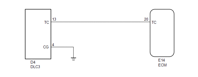
WIRING DIAGRAM
HINT:
When a particular warning light blinks continuously, a ground short in the wiring of terminal TC of the DLC3 or an internal ground short in the relevant ECU is suspected.
PROCEDURE
|
1. |
CHECK HARNESS AND CONNECTOR (TC of DLC3 - ECM) |
(a) Disconnect the E21 ECM connector.
(b) Measure the resistance according to the value(s) in the table below.
Standard Resistance:
|
Tester Connection |
Condition |
Specified Condition |
|---|---|---|
|
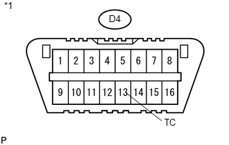
D4-13 (TC) - E14-20 (TC) |
Always |
Below 1 Ω |
(c) Reconnect the ECM connector.
| NG | .gif) |
REPAIR OR REPLACE HARNESS OR CONNECTOR |
|
.gif)
|
2. |
CHECK HARNESS AND CONNECTOR (TC of DLC3 - BODY GROUND) |
|
(a) Measure the resistance according to the value(s) in the table below. Standard Resistance:
|
|
| NG | |
REPAIR OR REPLACE HARNESS OR CONNECTOR |
|
|
3. |
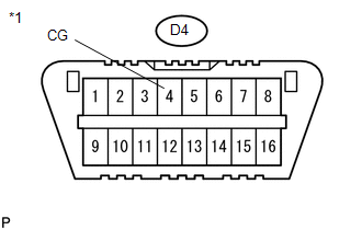
CHECK HARNESS AND CONNECTOR (CG of DLC3 - BODY GROUND) |
|
(a) Measure the resistance according to the value(s) in the table below. Standard Resistance:
|
|
| OK | |
REPLACE ECM |
| NG | |
REPAIR OR REPLACE HARNESS OR CONNECTOR |
 Cruise Main Indicator Light Circuit
DESCRIPTION
When the ECM detects a cruise control switch on signal from the cruise
control switch, the ECM sends the signal to the combination meter assembly
through CAN communication. ...

Other materials:
Terminals Of Ecu
TERMINALS OF ECU
1. CHECK DRIVER SIDE JUNCTION BLOCK AND MAIN BODY ECU (MULTIPLEX NETWORK BODY
ECU)
(a) Disconnect the MB main body ECU (multiplex network body ECU) connectors.
(b) Measure the voltage and resistance according to the value(s) in the table
below.
HINT:
Measure the values on ...
Lost Communication With ECM/PCM "A" Missing Message (U010087)
DESCRIPTION
The engine control unit and transmission control unit are located inside the
ECM. The engine control unit intercommunicates with the transmission control ECU
via CAN communication. If there is a problem in this intercommunication, the ECM
stores this DTC.
DTC Code
...
How To Proceed With Troubleshooting
CAUTION / NOTICE / HINT
HINT:
Use these procedures to troubleshoot the smart key system (for Start
Function).
*: Use the Techstream.
PROCEDURE
1.
VEHICLE BROUGHT TO WORKSHOP
NEXT
...
