Toyota Tacoma (2015-2018) Service Manual: Inspection
INSPECTION
PROCEDURE
1. INSPECT FRONT NO. 1 SPEAKER ASSEMBLY (w/o Amplifier Box Speaker Assembly)
(a) Measure the resistance according to the value(s) in the table below.
Standard resistance:
|
Tester Connection |
Condition |
Specified Condition |
|---|---|---|
|
1 - 2 |
Always |
3.2 to 4.8 Ω |
If the result is not as specified, replace the front No. 1 speaker assembly.
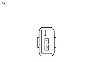
Text in Illustration|
*a |
Component without harness connected (Front No. 1 Speaker Assembly) |
2. INSPECT FRONT NO. 1 SPEAKER ASSEMBLY (w/ Amplifier Box Speaker Assembly)
(a) Measure the resistance according to the value(s) in the table below.
Standard resistance:
|
Tester Connection |
Condition |
Specified Condition |
|---|---|---|
|
1 - 2 |
Always |
1.4 to 2.2 Ω |
If the result is not as specified, replace the front No. 1 speaker assembly.
Text in Illustration|
*a |
Component without harness connected (Front No. 1 Speaker Assembly) |
 Removal
REMOVAL
CAUTION / NOTICE / HINT
HINT:
Use the same procedure for the RH and LH sides.
The procedure listed below is for the LH side.
PROCEDURE
1. REMOVE FRONT DOOR LOWER FRAME B ...
 Installation
INSTALLATION
CAUTION / NOTICE / HINT
HINT:
Use the same procedure for the RH and LH sides.
The procedure listed below is for the LH side.
PROCEDURE
1. INSTALL FRONT NO. 1 SPEAKE ...
Other materials:
Disassembly
DISASSEMBLY
PROCEDURE
1. REMOVE PRESSURE RELIEF VALVE
(a) Remove the pressure relief valve and O-ring.
2. REMOVE MAGNET CLUTCH ASSEMBLY
(a) Secure the cooler compressor assembly in a vise between aluminum plates.
(b) Using SST, hold the magnet clutch hub.
SST: 09985-00260
(c) Remove the ...
Installation
INSTALLATION
CAUTION / NOTICE / HINT
CAUTION:
Some of these service operations affect the SRS airbag system. Read the precautionary
notices concerning the SRS airbag system before servicing.
Click here
PROCEDURE
1. INSTALL FRONT SEAT INNER BELT ASSEMBLY
(a) for Driver Side:
(1) Install t ...
Trailer towing
Your vehicle is designed primarily as a passenger-and-load-carrying vehicle.
Towing a trailer can have an adverse impact on handling, performance, braking, durability,
and fuel consumption. For your safety and the safety of others, you must not overload
your vehicle or trailer. You must also e ...
