Toyota Tacoma (2015-2018) Service Manual: Radio Receiver Power Source Circuit
DESCRIPTION
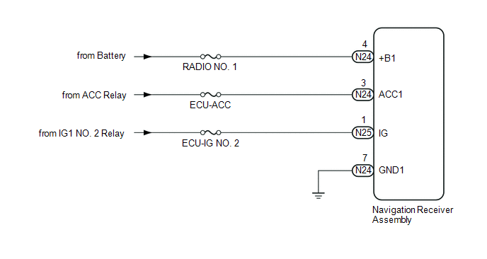
This is the power source circuit to operate the navigation receiver assembly.
WIRING DIAGRAM
CAUTION / NOTICE / HINT
NOTICE:
- Inspect the fuses for circuits related to this system before performing the following inspection procedure.
PROCEDURE
|
1. |
CHECK HARNESS AND CONNECTOR (NAVIGATION RECEIVER ASSEMBLY - BATTERY AND BODY GROUND) |
|
(a) Disconnect the N24 and N25 navigation receiver assembly connectors. |
|
(b) Measure the resistance according to the value(s) in the table below.
Standard Resistance:
|
Tester Connection |
Condition |
Specified Condition |
|---|---|---|
|
N24-7 (GND1) - Body ground |
Always |
Below 1 Ω |
(c) Measure the voltage according to the value(s) in the table below.
Standard Voltage:
|
Tester Connection |
Switch Condition |
Specified Condition |
|---|---|---|
|
N24-4 (+B1) - N24-7 (GND1) |
Always |
11 to 14 V |
|
N24-3 (ACC1) - N24-7 (GND1) |
Ignition switch ACC |
11 to 14 V |
|
N25-1 (IG) - N24-7 (GND1) |
Ignition switch ON |
11 to 14 V |
|
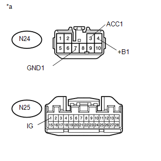
*a |
Front view of wire harness connector (to Navigation Receiver Assembly) |
| OK | .gif) |
PROCEED TO NEXT SUSPECTED AREA SHOWN IN PROBLEM SYMPTOMS TABLE |
| NG | |
REPAIR OR REPLACE HARNESS OR CONNECTOR |
 Microphone Circuit between Microphone and Radio Receiver
DESCRIPTION
The navigation receiver assembly and telephone microphone assembly are connected
to each other using the microphone connection detection signal lines.
Using this circuit, the navigatio ...
 Stereo Component Amplifier Power Source Circuit
DESCRIPTION
This circuit provides power to the stereo component amplifier assembly.
WIRING DIAGRAM
CAUTION / NOTICE / HINT
Inspect the fuses for circuits related to this system before performing ...
Other materials:
Coolant
Replacement
REPLACEMENT
PROCEDURE
1. REMOVE NO. 2 ENGINE UNDER COVER SUB-ASSEMBLY (w/ Off Road Package)
2. REMOVE NO. 1 ENGINE UNDER COVER SUB-ASSEMBLY
3. DRAIN ENGINE COOLANT
CAUTION:
Do not remove the radiator cap sub-assembly, cylinder block drain cock
plug or radiator drain ...
Installation
INSTALLATION
CAUTION / NOTICE / HINT
CAUTION:
Some of these service operations affect the SRS airbag system. Read the precautionary
notices concerning the SRS airbag system before servicing.
Click here
PROCEDURE
1. INSTALL FRONT SEAT INNER BELT ASSEMBLY
(a) for Driver Side:
(1) Install t ...
Inspection
INSPECTION
PROCEDURE
1. INSPECT WINDSHIELD WIPER SWITCH ASSEMBLY
(a) Check the resistance.
Text in Illustration
*a
Component without harness connected
(Windshield Wiper Switch Assembly)
(1) Measure the resistance according ...
