Toyota Tacoma manuals

Toyota Tacoma (2015-2018) Service Manual: Inspection

INSPECTION

PROCEDURE

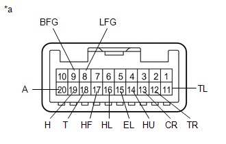
1. INSPECT HEADLIGHT DIMMER SWITCH ASSEMBLY

(a) Check the resistance.

(1) Measure the resistance according to the value(s) in the table below.

Text in Illustration

*a

Component without harness connected

(Headlight Dimmer Switch Assembly)

Standard Resistance:

Light Control Switch (w/o DRL OFF function)

Tester Connection

Switch Condition

Specified Condition

18 (T) - 15 (EL)

Light control switch OFF

10 kΩ or higher

19 (H) - 15 (EL)

10 kΩ or higher

18 (T) - 15 (EL)

Light control switch in tail position

Below 1 Ω

18 (T) - 15 (EL)

Light control switch in head position

Below 1 Ω

19 (H) - 15 (EL)

Below 1 Ω

Light Control Switch (w/ DRL OFF function)

Tester Connection

Switch Condition

Specified Condition

18 (T) - 15 (EL)

Light control switch DRL-OFF

10 kΩ or higher

19 (H) - 15 (EL)

10 kΩ or higher

20 (A) - 15 (EL)

10 kΩ or higher

18 (T) - 15 (EL)

Light control switch in tail position

Below 1 Ω

18 (T) - 15 (EL)

Light control switch in head position

Below 1 Ω

19 (H) - 15 (EL)

Below 1 Ω

20 (A) - 15 (EL)

Light control switch in AUTO position

Below 1 Ω

20 (A) - 15 (EL)

Light control switch in DRL position

Below 1 Ω

Dimmer Switch

Tester Connection

Switch Condition

Specified Condition

16 (HL) - 15 (EL)

Dimmer switch in low position

Below 1 Ω

14 (HU) - 15 (EL)

10 kΩ or higher

14 (HU) - 15 (EL)

Dimmer switch in high position

Below 1 Ω

14 (HU) - 15 (EL)

Dimmer switch in high flash position

Below 1 Ω

17 (HF) - 15 (EL)

Below 1 Ω

Turn Signal Switch

Tester Connection

Switch Condition

Specified Condition

12 (TR) - 15 (EL)

Neutral

10 kΩ or higher

11 (TL) - 15 (EL)

10 kΩ or higher

13 (CR) - 15 (EL)

10 kΩ or higher

12 (TR) - 15 (EL)

Right turn

Below 1 Ω

13 (CR) - 15 (EL)

Right turn fully

Below 1 Ω

11 (TL) - 15 (EL)

Left turn

Below 1 Ω

13 (CR) - 15 (EL)

Left turn fully

Below 1 Ω

Fog Light Switch

Tester Connection

Switch Condition

Specified Condition

9 (BFG) - 8 (LFG)

Fog light switch off

10 kΩ or higher

9 (BFG) - 8 (LFG)

Fog light switch in front position

Below 1 Ω

If the result is not as specified, replace the headlight dimmer switch assembly.

Removal
REMOVAL PROCEDURE 1. REMOVE SPIRAL CABLE WITH SENSOR SUB-ASSEMBLY (See page ) 2. REMOVE WINDSHIELD WIPER SWITCH ASSEMBLY 3. REMOVE HEADLIGHT DIMMER SWITCH ASSEMBLY (a) Disconnect ...

Installation
INSTALLATION PROCEDURE 1. INSTALL HEADLIGHT DIMMER SWITCH ASSEMBLY (a) Engage the 3 claws to install the headlight dimmer switch assembly. (b) Connect the connector. 2. INSTALL WINDSHIELD WIPER S ...

Other materials:

Speaker Circuit
DESCRIPTION If there is a short in a speaker circuit, the stereo component amplifier assembly*1 or navigation receiver assembly*2 detects it and stops output to the speakers. Thus sound cannot be heard from the speakers even if there is no malfunction in the stereo component amplifier assembly ...

Key-off Operation Function Operates even if Operating Conditions are not Satisfied
DESCRIPTION When the front doors are closed, each power window regulator motor assembly can control its power window operation for approximately 43 seconds after the ignition switch is turned from ON to off by receiving operation permission signals from the main body ECU. How ...

Diagnosis System
DIAGNOSIS SYSTEM 1. DESCRIPTION The ECU stores trouble codes when malfunctions occur. The diagnostic system allows for reading of the trouble codes from the DLC3. Use the Techstream to help diagnose and repair the problem. 2. CHECK DLC3 (a) Check the DLC3 (See page ). 3. INSPECT BATTERY VOLT ...

© 2011-2025 Copyright www.ttguide.net