Toyota Tacoma (2015-2018) Service Manual: System Description
SYSTEM DESCRIPTION
1. ENGINE IMMOBILISER SYSTEM DESCRIPTION
The engine immobiliser system is designed to prevent the vehicle from being stolen. This system uses the transponder key ECU assembly that stores the key ID codes of authorized ignition keys. If an attempt is made to start the engine using an unauthorized key, the transponder key ECU assembly sends a signal to the ECM to prohibit fuel delivery and ignition, effectively disabling the engine.
2. FUNCTION OF MAIN COMPONENTS
|
Component |
Outline |
|---|---|
|
Transponder key ECU assembly |
|
|
Transponder key coil |
When a key is inserted into the ignition key cylinder, the transponder key amplifier receives the key ID code from the transponder chip in the key grip and outputs it to the transponder key ECU assembly. |
|
ECM |
The ECM receives key ID code verification results from the transponder key ECU assembly. The ECM also verifies the ECUs. Then judgment of whether to immobilise the engine is made. |
|
Unlock warning switch assembly |
The unlock warning switch assembly detects if the key is in the ignition key cylinder and outputs the result to the transponder key ECU assembly. |
|
Security indicator light (air conditioning control assembly) |
Depending on the operation of the transponder key ECU assembly, the security indicator light comes on or starts blinking. |
3. SYSTEM FUNCTION
(a) When the transponder key ECU assembly detects that the unlock warning switch assembly is on, the transponder key ECU assembly applies current to the transponder key coil and produces a magnetic field around the antenna coil. A transponder chip in the key grip outputs a key ID code signal using electromotive force generated by the magnetic field. The transponder key coil receives the signal and sends it to the transponder key ECU assembly. The transponder key ECU assembly checks if the key ID code received from the transponder key coil matches the registered key ID code.
When the engine is started, the ECM communicates with the transponder key ECU assembly and checks the key verification result. In addition, the ECM checks if the engine ID codes stored in the transponder key ECU assembly and ECM match. If they do not match, the ECM prohibits engine start.
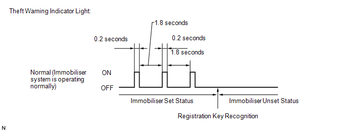
(b) The security indicator light blinking pattern is as shown below (when changing from the immobiliser set status to the unset status):
 Precaution
PRECAUTION
1. PRECAUTIONS WHEN USING TECHSTREAM
(a) When using the Techstream to troubleshoot the engine immobiliser system:
Connect the Techstream to the DLC3 while the ignition switch is off, and ...
 System Diagram
SYSTEM DIAGRAM
...
Other materials:
Rear Leaf Spring
Components
COMPONENTS
ILLUSTRATION
Disassembly
DISASSEMBLY
PROCEDURE
1. REMOVE BUSH
(a) Fix the spring in a vise.
(b) Using a hack saw, cut both ends off the bushes.
(c) Using SST and a press, press out the 2 bushes.
SST: 09950-60010
09951-00350
SST: 09950-70010
...
Diagnosis System
DIAGNOSIS SYSTEM
1. DESCRIPTION
(a) Smart key system (for entry function) data and Diagnostic Trouble Codes (DTCs)
can be read through the vehicle Data Link Connector 3 (DLC3). In some cases, a malfunction
may be occurring in the smart key system. When the system seems to be malfunctioning,
...
Inspection
INSPECTION
PROCEDURE
1. INSPECT OIL CLEARANCE
(a) Using a micrometer and caliper gauge, measure the oil seal clearance.
Standard clearance:
0.021 to 0.043 mm (0.0008 to 0.0017 in.)
Maximum clearance:
0.07 mm (0.0028 in.)
If it is greater than the maximum, replace the vane pump assembly.
...
