Toyota Tacoma (2015-2018) Service Manual: System Diagram
SYSTEM DIAGRAM
 System Description
SYSTEM DESCRIPTION
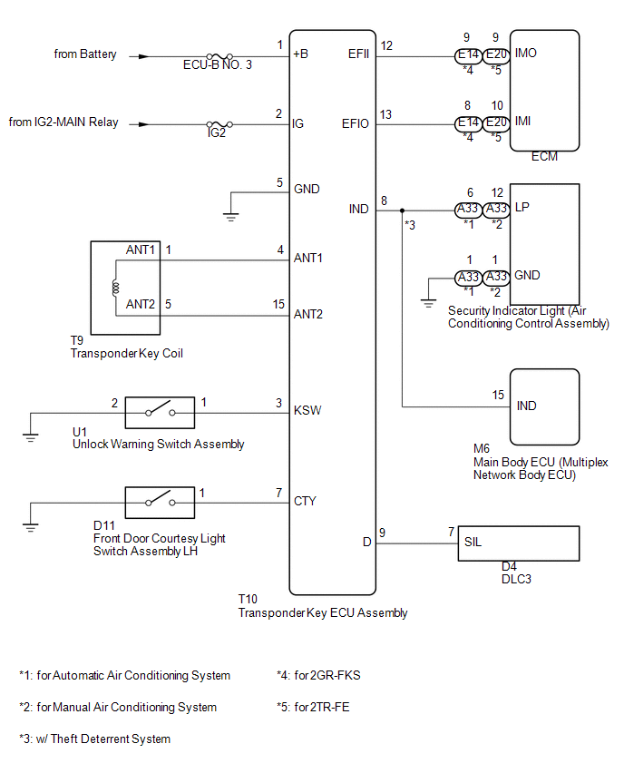
1. ENGINE IMMOBILISER SYSTEM DESCRIPTION
The engine immobiliser system is designed to prevent the vehicle from being stolen.
This system uses the transponder key ECU assembly th ...
 How To Proceed With Troubleshooting
CAUTION / NOTICE / HINT
HINT:
Use the following procedure to troubleshoot the engine immobiliser system.
*: Use the Techstream.
PROCEDURE
1.
VEHICLE BROUGHT TO WORKSHOP
...
Other materials:
Terminals Of Ecu
TERMINALS OF ECU
CHECK MILLIMETER WAVE RADAR SENSOR ASSEMBLY
(a) Measure the voltage and resistance according to the value(s) in the table
below.
Terminal No. (Symbol)
Wiring Color
Terminal Description
Condition
Specified Condition
...
Data List / Active Test
DATA LIST / ACTIVE TEST
1. DATA LIST
Using the Techstream to read the Data List allows the values or states of switches,
sensors, actuators and other items to be read without removing any parts. This non-intrusive
inspection can be very useful because intermittent conditions or signals may be ...
How To Proceed With Troubleshooting
CAUTION / NOTICE / HINT
HINT:
Perform the following procedure to troubleshoot the dynamic radar cruise
control system.
*: Use the Techstream.
PROCEDURE
1.
VEHICLE BROUGHT TO WORKSHOP
NEXT
...
