DISASSEMBLY
PROCEDURE
1. REMOVE OIL PUMP RELIEF VALVE
(a) Using a 27 mm socket wrench, remove the oil pump relief valve plug.
|
(b) Remove the oil pump relief valve spring and oil pump relief valve. |
|
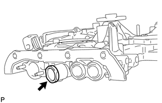
(c) Remove the spring and relief valve.
2. REMOVE OIL PUMP COVER
|
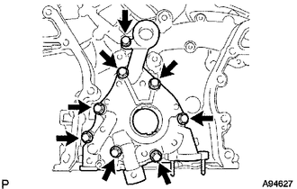
(a) Remove the 8 bolts, oil pump cover, drive rotor and driven rotor. |
|
Components
InspectionInstallation
INSTALLATION
PROCEDURE
1. INSTALL VANE PUMP
(a) Install the vane pump assembly with the 2 bolts.
Torque:
21 N·m {214 kgf·cm, 15 ft·lbf}
(b) Connect the oil pressure switch connector.
NOTICE:
Make sure that no oil adheres to the connector.
...
Installation
INSTALLATION
CAUTION / NOTICE / HINT
HINT:
Use the same procedure for both the RH and LH sides.
The procedure described below is for the LH side.
PROCEDURE
1. INSTALL FRONT SHOULDER BELT ANCHOR ADJUSTER ASSEMBLY
(a) As shown in the illustration, engage the 2 guides ...
Stereo Component Amplifier Malfunction (B15A3)
DESCRIPTION
This DTC is stored when a malfunction occurs in the stereo component amplifier
assembly.
DTC No.
DTC Detection Condition
Trouble Area
B15A3
When one of the conditions below is met:
Internal power supply malfun ...